Pneumatic Control Valve: How the Process Valve, Actuator and Positioner Work Together
Pneumatic Control Valve: How the Process Valve, Actuator and Positioner Work Together
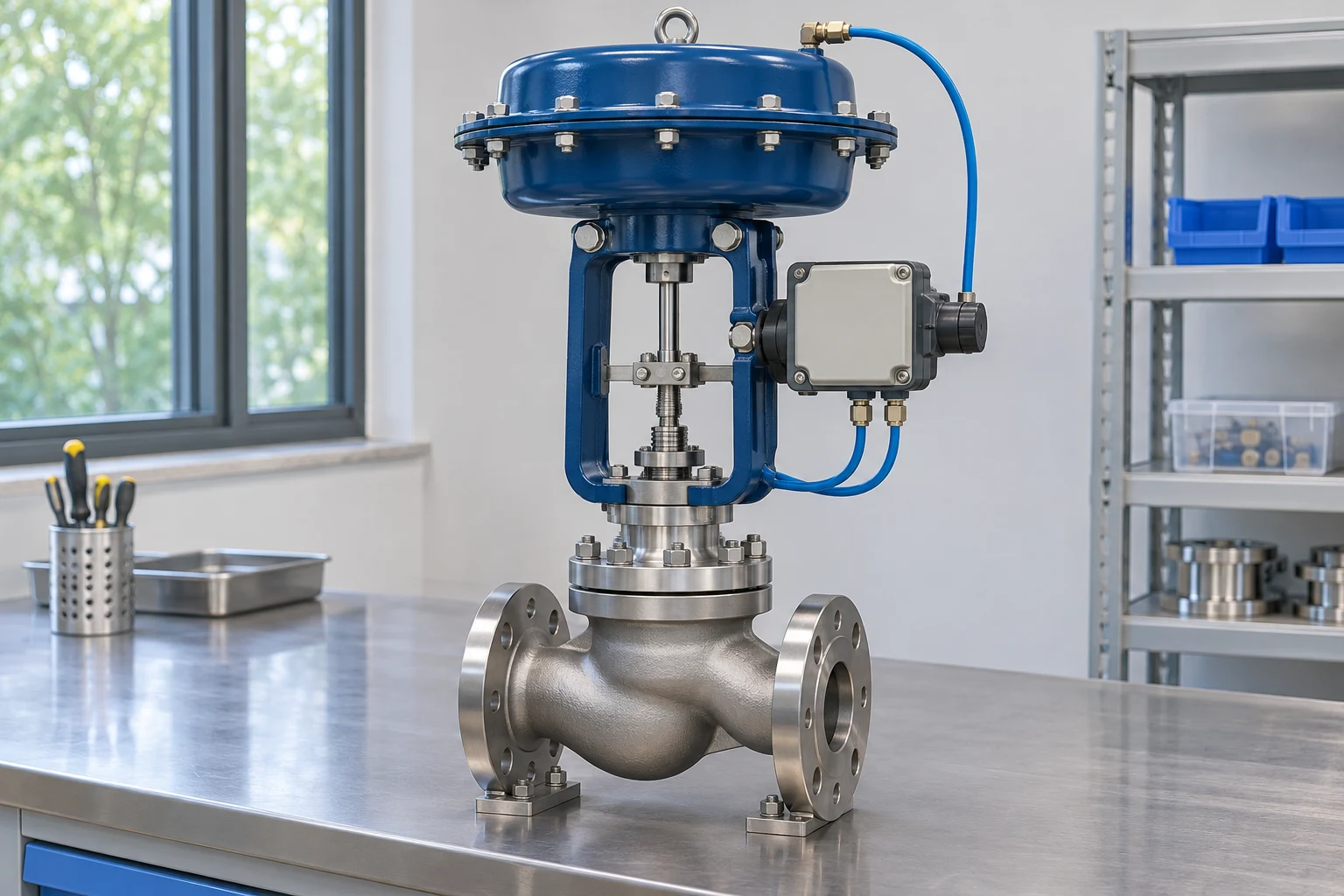
A pneumatic control valve uses compressed air to move a valve that regulates a process fluid. The air usually operates an actuator outside the process pressure boundary; the process fluid passes through the valve body and trim. A controller requests a position, and a positioner where fitted adjusts actuator pressure to achieve that position.
This is different from a directional air valve that switches compressed air between cylinder ports. Both are pneumatic equipment, but they control different paths. Here the subject is a process regulating assembly for a liquid, gas or steam line, with air providing the operating force.
Three selections must work together: the trim must handle the process conditions, the actuator must move it under load, and the control accessories must produce the required response. A large actuator cannot correct an unsuitable trim, and a smart positioner cannot make an oversized valve control well at every demand.
Follow the Process Path and the Air Path Separately
The process path runs from the upstream pipe through the valve's restriction to the downstream pipe. The body contains the medium; the plug, disc or other trim changes the effective opening. The process pressure, temperature, composition and flow conditions determine what that construction must withstand.
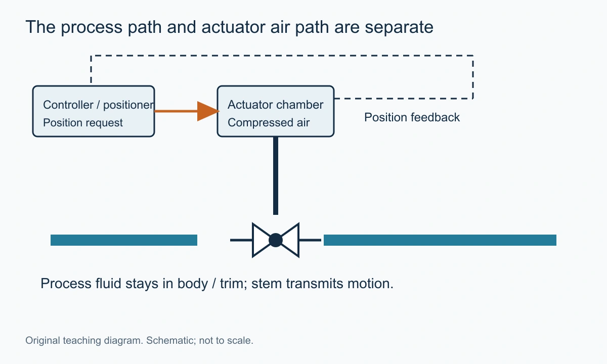
The air path begins at an instrument-air supply and passes through the specified preparation and control equipment to the actuator. Air pressure acting on a diaphragm or piston creates force. An exhaust route permits pressure to leave when the actuator must move in the other direction or respond to a defined event.
An electrical signal may connect the controller to an electropneumatic positioner. The signal carries the requested movement, while the air supplies operating energy. Confusing those roles makes troubleshooting difficult: a correct signal does not prove adequate air delivery, and adequate air does not prove the commanded position is correct.
The VantaValve control valve category is the product-family starting point. For a new enquiry, provide the process duty and available air and signal separately so the complete assembly can be evaluated.
Main Components of the Assembly
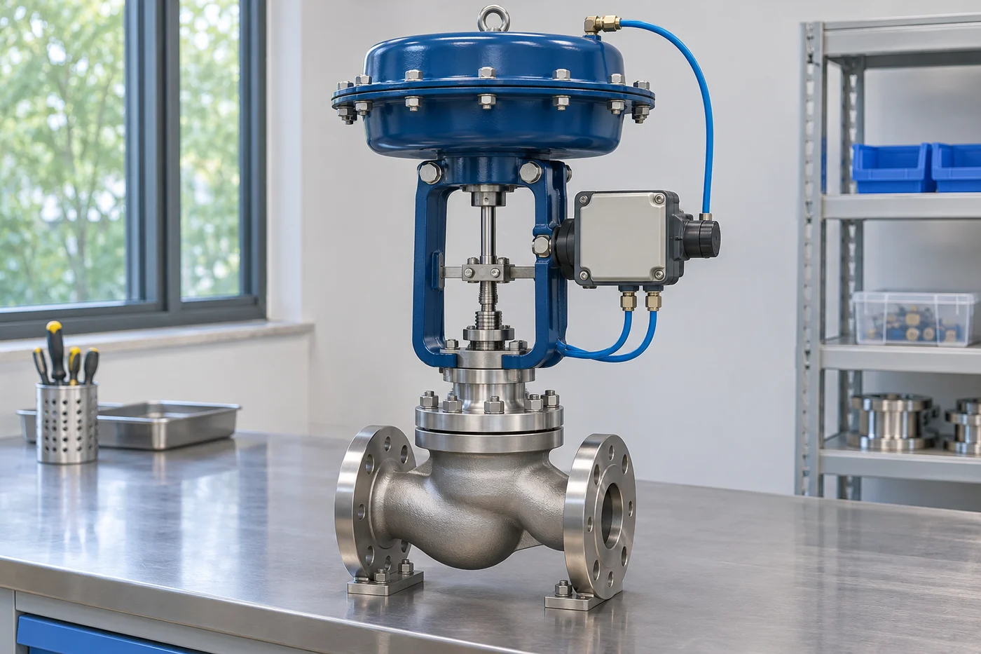
The valve body and trim create the controlled passage. The actuator supplies movement. The positioner compares requested and measured position. Accessories add particular functions such as supply regulation, switching, indication or increased air delivery. Each component should have an identifiable job.
Valve Body and Trim
A globe construction is a familiar choice for many regulating duties because plug movement can deliberately change the seat opening. Rotary constructions can also regulate where their geometry and service suitability fit. Pneumatic describes the operator, not a universal valve-body pattern.
The selected trim determines capacity, characteristic and important pressure-reduction behaviour. Reduced-capacity trim can give a suitable operating region in a body selected for the connection or mechanical requirement. A larger full-capacity port is not automatically an improvement when normal demand is small.
The globe valve family is relevant where a linear plug-and-seat arrangement is being considered. A particular assembly still needs sizing for the actual fluid, differential and operating range, including possible phase change or compressible-flow limits.
Diaphragm and Piston Actuators
A diaphragm actuator creates force over an effective area. Springs can oppose that force and establish a specified movement when pressure is relieved. A piston actuator uses pressure acting on a piston and may be single-acting with a return mechanism or double-acting with pressure applied to opposing sides.
The useful comparison is available output across the required movement. Area, pressure, spring force, friction and travel all matter. The outside diameter of a housing is not the effective pressure area, and the maximum permitted pressure is not the pressure necessarily used at every operating position.
SAMSON's Type3271/3277 actuator datasheet, edition May2026, provides a manufacturer example with several effective areas and bench ranges. The document also gives configuration-dependent supply restrictions. Its data show why an actuator's exact assembly matters; they are not universal ratings for pneumatic actuators.
Positioner and Position Feedback
A positioner compares a requested position with measured valve movement and adjusts its pneumatic output to reduce the difference. It creates an inner position loop within the larger process-control loop. The process controller may be regulating temperature while the positioner is regulating stem position.
This distinction is useful when the process does not follow the command. The valve can reach its requested position while the process flow remains different from the expected value because pressure conditions have changed. Accurate positioning is valuable, but it does not turn position into a direct flow measurement.
Position feedback can also have limits. The sensed point may be on an actuator or linkage rather than directly measuring every internal sealing contact. A reported closed position and a specified seat-leakage performance remain different observations. Interpret diagnostic data in terms of what the instrument actually measures.
Air Preparation, Solenoids and Boosters
A supply regulator establishes the permitted air condition for the assembly. Filtration and moisture control address contamination that could affect small pneumatic passages. The required air quality should follow the selected equipment's instructions and the site's instrument-air specification.
A solenoid valve can switch or vent an air path under a defined command. Its location and normal state influence what happens on electrical loss. It should not be described as the positioner simply because both affect actuator pressure; switching and proportional positioning are different functions.
A volume booster can increase air delivery or exhaust capacity for a suitable arrangement. It is not a generic cure for slow response. Its configuration and adjustment can affect stability, and it still depends on adequate upstream air delivery. Accessory selection should follow the required dynamic response.
How the Two Control Loops Work
Consider a temperature-controlled heat exchanger. A transmitter measures the process temperature and sends it to a controller. The controller compares the measurement with the setpoint and changes its output to request more or less heating-medium flow through the control valve.
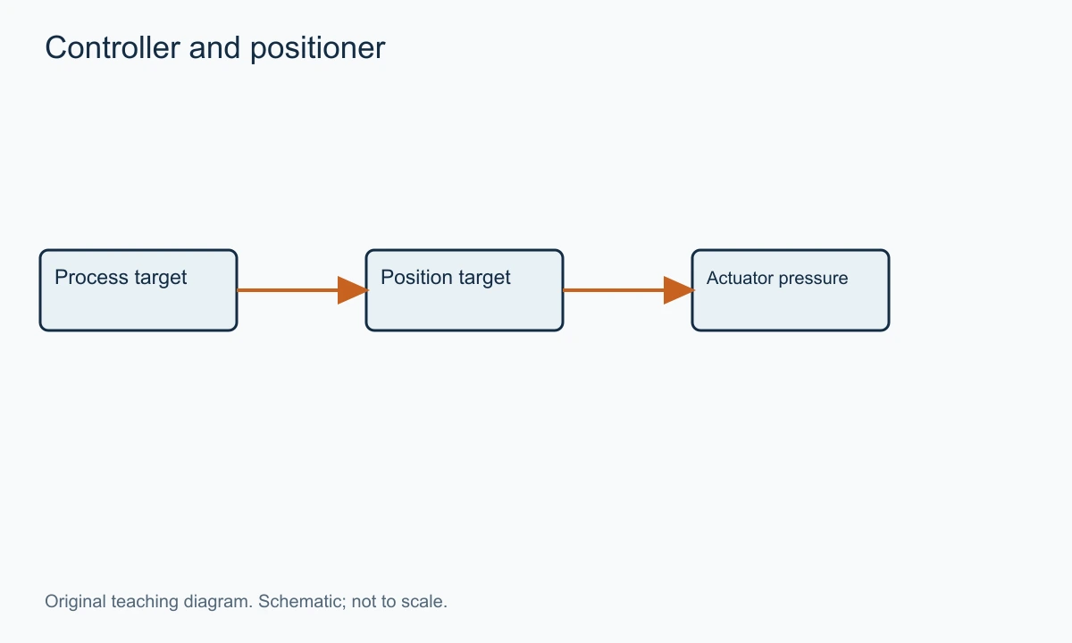
The positioner receives the requested position and compares it with actual movement. If they differ, it admits or exhausts actuator air until the requested position is approached. The actuator moves the trim, changing the process restriction. The process responds, and the transmitter reports the result to the controller.
The process loop and position loop operate on different variables. A positioner can correct some effects of mechanical resistance on movement, but it cannot independently decide the desired process temperature. Conversely, the process controller should not have to overcome every small movement error by accumulating a larger command.
Delay exists in several places: sensing, signal transmission, pneumatic filling, mechanical movement and the process itself. Increasing one component's speed does not automatically improve the whole loop. A very rapid valve on a slow thermal process may still need appropriate controller tuning and a suitable operating range.
The practical objective is a consistent, controllable response. Specify the movement and process requirement rather than simply requesting the fastest actuator or the most advanced positioner available.
Supply Pressure, Bench Range and Control Signal Are Different Values
Supply pressure is the air available to the positioner or actuator arrangement. Bench range describes a specified actuator spring-and-travel relationship under its defined unloaded or test conditions. A control signal expresses a request. These values may all appear on a datasheet, but they cannot be substituted for one another.
For an electropneumatic assembly, a 4–20 mA signal is a common form of request. It does not mean that the actuator pressure must be 0.2–1.0 bar, nor that every signal value corresponds to one fixed pressure under load. The positioner output adjusts to produce the requested movement within the assembly's limits.
Similarly, a plant air header at 6 bar does not mean every actuator chamber should receive 6 bar. The selected equipment has maximum pressures and may require a regulated supply. A pressure sufficient for one actuator configuration can exceed the permitted value of another.
A bench range can help describe spring action, but process forces change the installed balance. A valve that strokes as expected on an unloaded bench may need a different pressure at the same travel when installed under differential. Actuator selection should include that load rather than rely on the unloaded relationship alone.
The distinction also matters during diagnosis. A pressure gauge at the air header cannot prove that the actuator receives adequate pressure during a rapid movement. Restrictions, tubing and accessory flow can cause a local pressure reduction while the remote gauge looks satisfactory.
A Transparent Actuator-Force Example
Assume an illustrative diaphragm has an effective area of 350 cm², equal to 0.035m². At an actuator differential of 0.6 bar, or 60,000Pa, the gross pressure force is 2,100N. This is pressure multiplied by effective area; it is not the net thrust available to move the process plug.
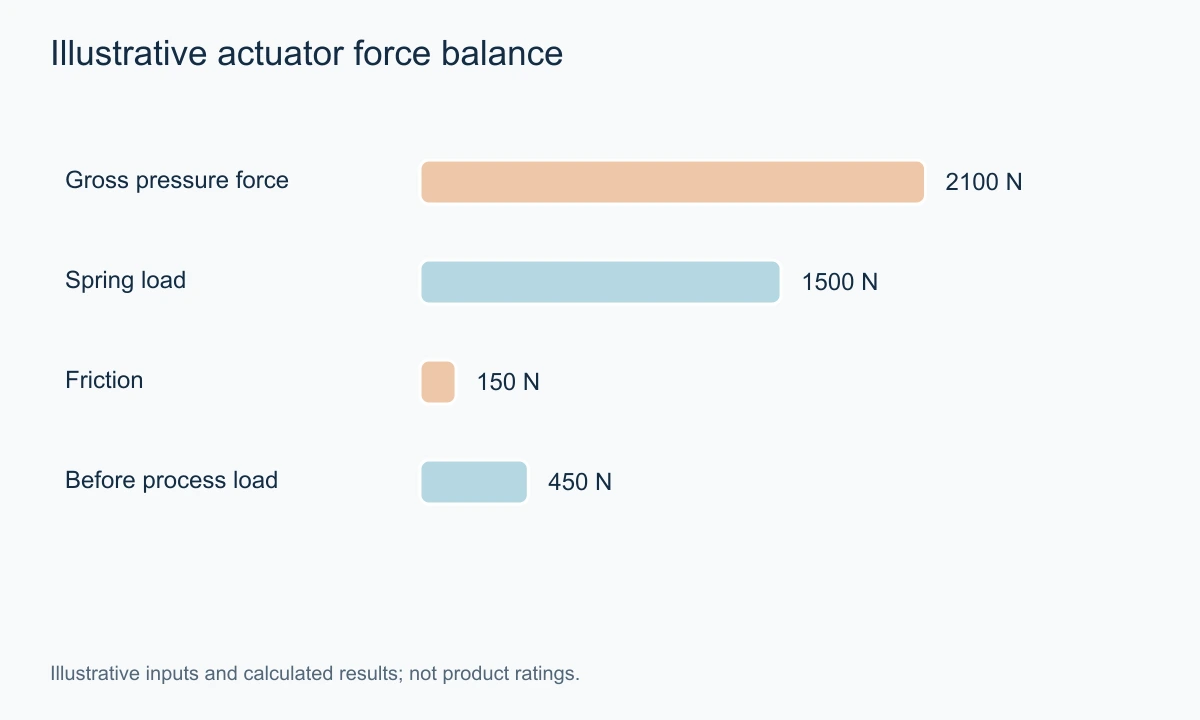
Suppose the spring force at that position is 1,500N and mechanical friction is estimated at 150N for this example. The remaining force is 450N before considering the process force that the actuator must overcome or control. If the process contributes an opposing 700N, this assumed operating point does not provide enough net force.
Increasing chamber pressure to 0.8 bar would make the gross force 2,800N with the same assumed effective area. If the spring and friction values remained the same at the evaluated position, the remaining force would be 1,150N before process loading. The calculation explains the sensitivity, but it is not an instruction to raise a real supply pressure.
Actual spring force changes with travel, friction is not always constant, and the effective pressure area and process loading require the selected design's data. The actuator and valve also have permitted pressures and structural loads. A complete selection checks the stroke and both required directions, not one favourable point.
| Illustrative input | Value used |
|---|---|
| Effective diaphragm area | 350 cm² = 0.035m² |
| Chamber differential | 0.6 bar = 60,000Pa |
| Gross pressure force | 2,100N |
| Assumed spring force at evaluated position | 1,500N |
| Assumed friction | 150N |
| Remaining force before process load | 450N |
The example gives a useful enquiry question: what output remains after the spring, friction and actual process forces are included at the limiting position? A housing-size label or a maximum supply value cannot answer that alone.
Fail-Open, Fail-Closed and the Defined Failure Event
Failure action should be stated for the complete assembly and a specific event. Loss of instrument air, loss of the electrical request, loss of solenoid power and a mechanical jam are different conditions. A label that says only fail safe can hide which one has been evaluated.
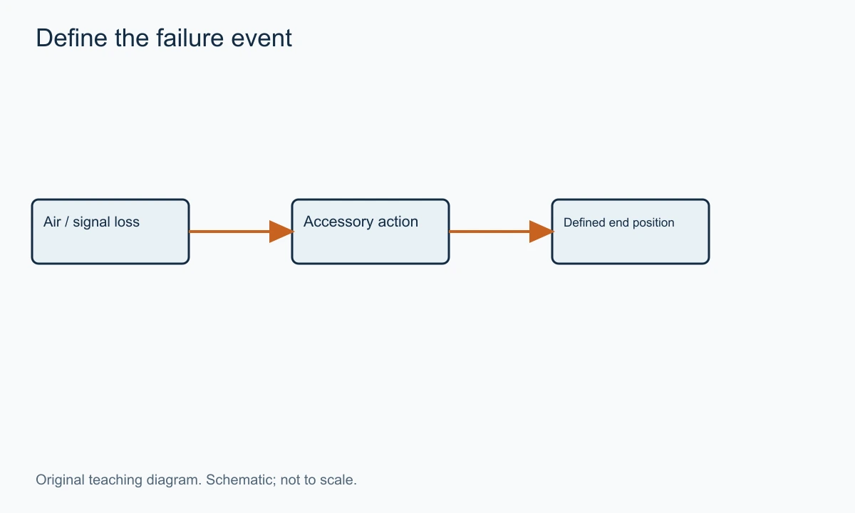
For a spring-return linear assembly, relieving the relevant chamber allows springs to move the actuator toward its designed end position. Whether that closes or opens the process passage depends on the actuator arrangement and valve action. Stem extends and valve closes are not universal synonyms across every valve construction.
SAMSON's Type3241 control-valve datasheet, edition November2022, describes the fail-open and fail-closed arrangements for its specified globe valve and actuators. That is an example of assembly-specific action. The statement should not be transferred to a different rotary valve or reversed trim without evaluation.
The air route matters too. If an accessory traps pressure, the valve may not immediately follow the movement expected from simply removing the air source upstream. If an exhaust path is restricted, the movement time can change. The required action should therefore be checked against the complete pneumatic schematic.
A double-acting actuator may require additional equipment to provide a defined stored-energy movement. Without that arrangement, it should not be assumed to behave like a spring-return assembly on supply loss. State the required position and time, then identify how the assembly achieves it.
A defined failure action is one part of a larger protection function where applicable. It does not by itself establish a safety-system capability, proof-test interval or system integrity. Use the project's required assessment and the actual equipment evidence for those decisions.
Size the Trim Before Treating the Actuator as the Solution
The trim must pass the required maximum flow and retain useful control at lower demand. Oversizing can put most operation close to the seat, where a small movement may produce a large change relative to the required flow. More actuator force does not remove that capacity mismatch.
For an appropriate incompressible-liquid calculation, the operating capacity can be expressed as Kv = Q√(SG/Δp). The Cv and Kv guide explains the units and limits. Provide paired flow and pressure conditions for minimum, normal and maximum cases, rather than one flow and an unrelated maximum differential.
The selected characteristic then relates capacity to travel under its defined basis. The installed response includes the rest of the system, which can change the differential as the valve moves. A linear inherent characteristic does not guarantee a linear relationship between command and process flow after installation.
Gas, steam and possible phase-change liquid duties require the applicable sizing method. Capacity, noise, cavitation or flashing, and outlet velocity can constrain the selection. A successful stroke test cannot establish that the trim is suitable for those process conditions.
The chemical-processing and power-generation routes can help organise the service discussion. Specify the actual duty within the industry rather than assume one pneumatic assembly suits every line at the site.
Friction, Deadband and Hunting
Mechanical friction can keep the stem from moving until the applied force exceeds a threshold. Once movement begins, the force balance can change and the stem may move farther than expected. The resulting stick-and-move behaviour can be difficult for a process controller to manage.
Deadband describes a region of input change that does not produce the expected reversal or output response under its defined measurement. It should be considered with the actual assembly and test method. A catalogue number for a positioner alone does not establish the behaviour of the installed valve, linkage and packing.
Hunting is repeated movement around an operating condition. It can arise from several causes, including control tuning, excessive capacity, mechanical resistance or pneumatic accessory behaviour. Calling every oscillation a positioner problem skips the evidence needed to find the cause.
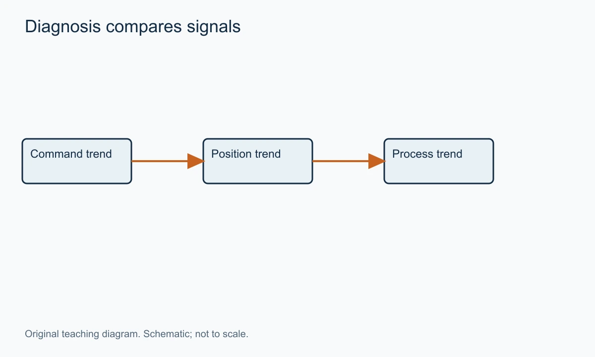
A useful record compares command, measured position and process response over time. If command changes while position does not, the movement path deserves attention. If position follows command while the process oscillates, the process loop and sizing conditions require another look. The signals help localise the problem without making a diagnosis from sound or appearance alone.
Maintenance changes can alter the behaviour. Packing work, linkage adjustment or a changed supply regulator setting can affect movement. Record what changed and compare with the selected procedure before compensating through controller tuning or increased pressure.
Response Time and Air Delivery
An actuator chamber must receive or release air to move. The time depends on chamber volume, pressure, tubing, restrictions, positioner capacity and accessories. A large actuator can require substantial air delivery even when its steady holding consumption is modest.
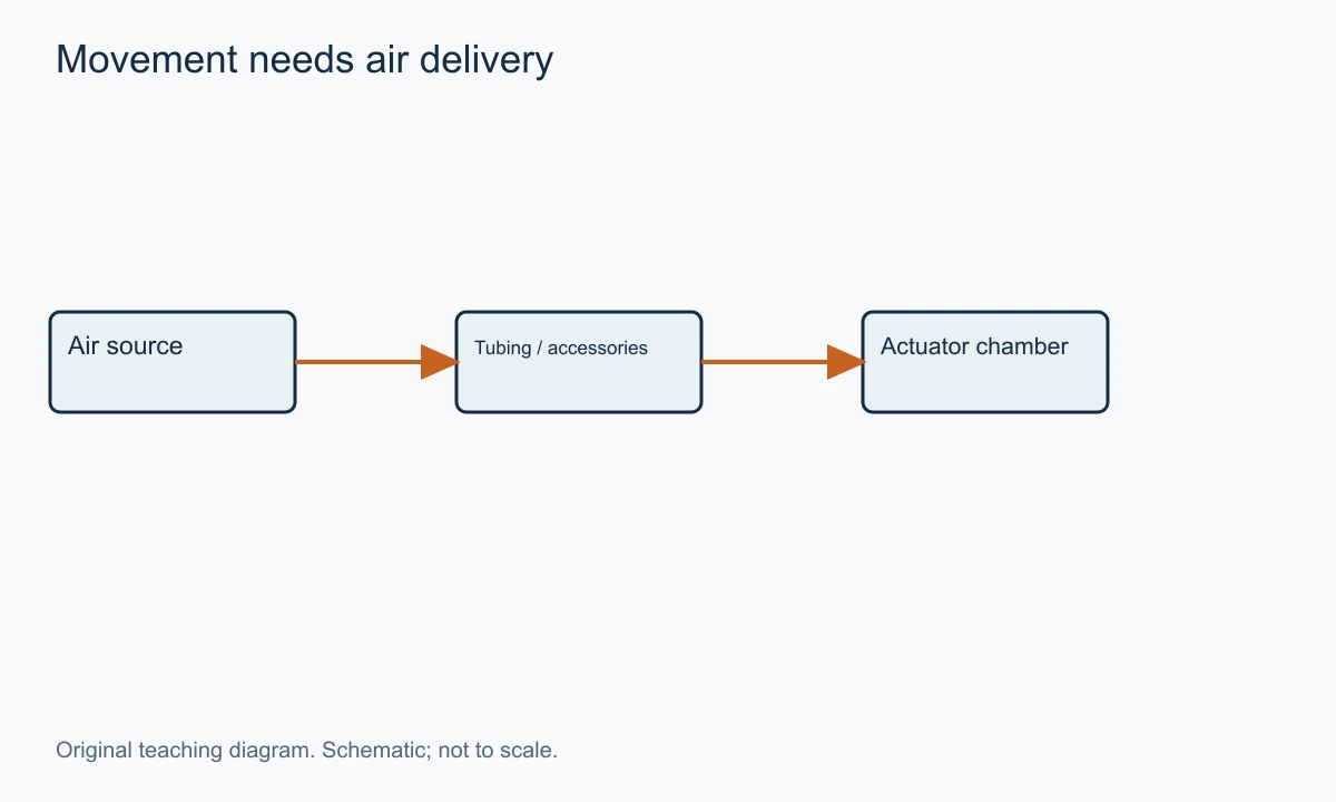
Separate steady consumption from the air used during movement. A quoted bleed or steady consumption value does not necessarily describe peak stroking demand. The air system must support the required movement without falling below the specified supply condition at the assembly.
Tubing length and bore matter because they affect delivery and exhaust. A remote manifold can simplify layout while creating a different pneumatic path. Assess the selected arrangement rather than assume a bench stroke time remains unchanged after long tubing is added.
A booster can be appropriate where the response requirement and equipment design support it. Its settings and bypass arrangement can affect stability. Faster filling and exhaust should be evaluated alongside the valve's mechanical limits and the process consequence of rapid movement.
For a liquid system, closing time may influence pressure transients. For a thermal loop, excessive speed may provide little benefit relative to the process delay. The required response is therefore a process decision expressed as a movement requirement, not a contest for the shortest catalogue time.
Trace a Four-to-Twenty-Milliamp Request Without Confusing It With Air Pressure
A configured linear signal map can express a requested travel over a four-to-twenty-milliamp span. Under that explicit assumption, the requested percentage is the current minus four, divided by sixteen, multiplied by one hundred. Eight milliamps represents twenty-five percent, twelve represents fifty percent and sixteen represents seventy-five percent.
Those are requested positions under the assumed configuration. A reverse-acting map can use another relationship, and a positioner can have configured characterisation or limits. The actual settings should be retained with the assembly so the numerical request is interpreted correctly.
The current does not supply the mechanical energy needed to push the plug through the process differential. The positioner uses the available air to produce the necessary actuator pressure within its permitted envelope. At the same requested position, the output pressure can change when the process force changes.
That is why a pressure reading cannot always be converted back into travel through an unloaded bench range. A loaded valve has another force balance. The positioner can admit more air to hold a requested position against an increased opposing load, while the position remains unchanged.
The distinction is useful during an instrument check. Establish the requested position from the configured signal map, compare it with measured movement, and then interpret pneumatic pressures in terms of the loaded assembly. Do not assume one fixed air pressure must correspond to every occurrence of fifty-percent command.
A signal below the configured live range can also have a defined diagnostic or failure meaning in the selected system. That response belongs to the instrument configuration and assembly documentation. It should not be invented from the normal linear map or treated as the same event as physically losing the air supply.
Available Thrust Changes Across the Stroke
A spring-return actuator's spring force changes with compression. The process force on the plug can also change with position and differential. The limiting point is therefore not necessarily the fully closed position or the point used in a simple gross-force example.
Consider an illustrative requirement with three positions. Near opening, the assembly must overcome a high breakaway load. At mid-travel, mechanical friction and the process force dominate. Near closure, the required seating load rises. A candidate that satisfies the middle point can still fail to unseat or fail to develop the required final contact.
The return direction needs its own comparison. With chamber pressure relieved, the springs provide the movement, but process forces may assist or oppose it. The available spring output has to cover the relevant resistance throughout the required return stroke. A satisfactory air-driven movement is not proof of a satisfactory spring-driven response.
A larger effective area can provide more pressure force at the same chamber differential. It can also change chamber volume and the air-delivery requirement. The selection should therefore compare force, travel and response together. Increasing area is not a cost-free answer to every operating problem.
The mechanical limit matters at the other end. An actuator capable of a large output can exceed what a stem, coupling or seating arrangement should receive if its settings are inappropriate. The required output and maximum permissible load form an operating envelope, not a target to exceed by the largest possible margin.
The useful supplier result is a documented assembly assessment under the limiting operating cases. It should identify the available supply, spring arrangement, required travel, process forces and seating requirement. A single housing diameter or maximum-pressure number cannot establish that result.
Why an Unloaded Stroke Test and a Loaded Test Answer Different Questions
An unloaded movement test can establish whether the assembled linkage moves through its configured travel and whether indication follows. It can reveal a reversed action, a disconnected feedback linkage or an incorrectly set limit. Those are valuable observations before the process is involved.
The process adds forces and another set of physical conditions. A valve that moves freely without differential can require more thrust under the actual pressure drop. A hot service can also change friction or the mechanical relationship from the cold test condition. The unloaded result should be retained without being overinterpreted.
A controlled loaded acceptance observation can then evaluate movement and regulation under the approved operating cases. The purpose is not to repeat the same test ceremonially; it is to add the conditions absent from the bench. The selected procedure should identify which cases and limits it evaluates.
The same distinction applies to closing. Reaching the mechanical or indicated end position is one observation. Meeting the specified internal leakage basis is another. A positioner diagnostic can help explain movement while a separate test establishes seat performance under its defined condition.
Recording the test basis prevents misleading comparisons later. A maintenance technician comparing a cold unloaded stroke time with a hot loaded operating movement may observe a real difference without having evidence of a defect. The conditions determine whether the values should match.
An Original Signal-and-Position Diagnostic Example
Assume a teaching example in which the controller requests forty, forty-one, forty-two and forty-three percent travel at successive intervals. The measured stem remains near thirty-eight percent, then jumps toward forty-six percent. These are invented observations used to explain a diagnostic method, not a record from an installed valve.
The difference between command and movement suggests that the movement path deserves investigation. Friction is one possible contributor, but the observations alone do not prove packing stiction. Supply limitations, feedback linkage or another mechanical issue could produce a discrepancy. The selected controlled checks should separate those possibilities.
Now consider another illustrative trend: measured position follows every requested step closely, but the process temperature oscillates slowly. That directs attention toward the outer process loop, sizing, measurement and system delay rather than assuming the actuator is failing to reach position.
A third example shows normal movement at steady plant conditions but slow movement when several pneumatic users operate together. Compare the supply pressure at the assembly during that event. A remote air-header reading can miss a local delivery limitation through tubing or accessories.
The point is to compare related traces on one time basis. Command, measured position, local air condition and process response each answer a different part of the question. Looking at one maximum value from each at unrelated times can create an apparent explanation that never existed during the actual event.
A useful diagnostic report states the observed relationship and the remaining hypotheses. It does not label every oscillation hunting caused by the positioner, or every delay an undersized actuator. That restraint makes the next technical check more specific, rather than leaving the reader with a generic list of possible faults.
Actuator Volume and Peak Air Demand
Moving a pneumatic actuator requires a change in the mass of air in its chamber. Chamber volume, pressure and temperature define that quantity, while restrictions determine how quickly the change can occur. A steady air-consumption value does not describe the complete stroking demand.
A simplified ideal-gas comparison can show the scale. Assume a chamber of two litres is filled from one bar absolute to four bar absolute at the same temperature, with volume held constant for this explanatory estimate. The added air mass corresponds to roughly six litres at one bar absolute and that temperature: two litres multiplied by the three-bar absolute pressure increase divided by the one-bar reference.
A real moving actuator changes chamber volume during travel, and the actual supply and exhaust dynamics require another assessment. The example is not an air-receiver sizing method. It demonstrates why a small steady bleed and a much larger brief movement demand can both belong to the same assembly.
If the required movement time is short, that added mass has to pass through the selected tubing and accessories quickly enough. A small restriction can create a pressure difference during the fill even though the pressures equalise later. A gauge read only after movement can miss the limiting condition.
Exhaust deserves the same attention as filling. A restricted vent can slow the movement driven by springs or opposing pressure. Weather protection, silencers or other fittings should be selected and maintained according to their actual function rather than added without considering the pneumatic path.
This explains why a volume booster is sometimes useful, while preserving the selection question. It changes delivery or exhaust capability in an appropriate arrangement; it does not create an adequate upstream source or remove mechanical resistance. The complete response should be checked with the selected configuration.
Air-to-Open Is an Assembly Relationship
Air-to-open describes the direction of movement produced by increasing the relevant actuator pressure in the specified assembly. For a common spring-return globe arrangement, the associated spring action can close the valve when that pressure is relieved. Another valve or linkage can create a different process relationship.
Do not translate actuator stem extension directly into process closure without checking the trim action. The actuator supplies movement; the valve mechanism determines what that movement does to the passage. The assembled drawing and functional description connect those two statements.
Accessories can further change the response to an electrical event. A solenoid may vent, supply or block a particular air path according to its configuration. Loss of its power can therefore be different from a normal controller request to zero percent travel. Both should be defined where they matter to the process.
A handwheel or manual override can also affect the permitted operating state. Its position and use should follow the selected procedure so it does not unintentionally prevent the required automatic movement. The presence of an override is an additional function, not evidence that every operating mode is interchangeable.
For a multiport or rotary assembly, describe the resulting route or disc position explicitly. A phrase such as fail open may be insufficient if several ports or paths exist. The required process state should be unambiguous before it is translated into actuator action.
Position Characterisation Cannot Repair Every Sizing Error
A positioner can apply a configured relationship between input and requested movement. That can be useful within a selected control strategy. It does not change the physical maximum passage, the local velocity at a small opening or the available actuator force.
An oversized trim may require most useful regulation in a narrow travel region. Remapping the command can spread that small region over more of the input range, but it does not automatically improve the valve's physical resolution, friction behaviour or pressure-reduction duty. The underlying trim and process cases still need review.
The same limitation applies to aggressive controller tuning. A controller can change its demand more strongly, but it cannot make an actuator overcome a pressure or mechanical limit beyond its selected envelope. If movement saturates, the process loop needs to account for that physical boundary rather than continually demand an impossible response.
For a changed plant duty, revisit the actual minimum and maximum cases before adjusting every layer of control. A different port or trim can sometimes address the physical mismatch, while another application needs a system change. The appropriate result follows the mechanism identified by the data.
Keep the selected signal map, travel limits and trim identity together in the record. Otherwise a later configuration reset can remove a deliberate mapping, or a trim replacement can change capacity while preserving settings intended for another assembly. The mechanical and configured functions must remain connected.
Commissioning Records That Support Later Diagnosis
A useful commissioning record identifies the selected valve, trim, actuator, spring arrangement, positioner and accessories. It also records the supply condition, configured travel and required action. This gives later maintenance a baseline that belongs to the actual assembly.
Confirming the commanded travel and feedback is a different task from confirming process performance. An unloaded movement check can find linkage or configuration errors. Operation under the approved process conditions then establishes whether the selected assembly controls as required. Keep those observations distinct.
Where a defined failure action is part of acceptance, verify it through the approved procedure for the specified event. Record the event applied, the resulting movement and any time requirement. A normal command to close is not the same test as loss of the relevant energy or signal.
The documentation guide helps organise the record. Include software settings where they affect the positioner, but do not let a settings export replace the mechanical identity and process datasheet.
For an installed problem, a clear baseline can prevent a cycle of replacing components without finding a changed condition. The new pump, higher flow or altered pressure may be more relevant than the age of the positioner.
Normal Differential Can Hide the Maximum Closing Load
A valve's normal regulating differential can be much smaller than the differential it must close against in another defined condition. Actuator selection should use the relevant operating and shutoff cases rather than one normal pressure drop.
Assume an illustrative upstream pressure of six bar and a normal downstream pressure of five bar. The normal differential is one bar. If the downstream side can fall to zero gauge pressure during a defined closing case while the upstream remains at six bar, the differential is six bar.
For the same assumed effective unbalanced area, the pressure-force term is six times as large in the second case. This is a relationship between stated example conditions, not a claim that every actuator needs six times the total thrust. Friction, springs and seating load remain part of the actual balance.
The example explains why a valve can regulate normally yet struggle with a particular closure. A larger normal flow coefficient would not solve the missing force. The assembly needs the actual maximum differential and direction included in its selection.
For a balanced trim, another force relationship applies, but the operating-case requirement remains. The selected design's balancing arrangement and seals establish the residual forces and any applicable limits. Balanced should not be used as shorthand for ignoring the shutoff case.
Electrical Configuration and Pneumatic Action Must Agree
An electropneumatic positioner receives an electrical request and produces a pneumatic output according to its configured function. The control system, instrument and actuator can each have a direction or failure setting. Their combined result must match the process action.
A reversed electrical map can be legitimate if it is deliberately configured and documented. It becomes a problem when one document expects an increasing signal to open while another expects it to close. The physical valve may operate correctly while the system's interpretation is wrong.
The selected positioner's manual also defines responses outside normal operation. SAMSON’s safety-related positioner documentation, for example, distinguishes emergency venting through its specified paths and the spring-dependent actuator end position. Those functions belong to the named arrangement and do not establish one universal response for every smart positioner.
The useful acceptance record states the input applied, the configured action and the resulting movement. It should distinguish a normal travel request from a defined signal-loss or venting event. That makes later comparison possible without guessing which test was performed.
An enclosure or communication option adds another specification layer. A digital communication capability can support setup and diagnostics, but it does not change the basic requirement for a correct air path and loaded movement. Treat those features as useful functions with a stated purpose rather than evidence of inherently better process control.
Preserve the Mechanical Reference After Maintenance
A stem connector, feedback linkage or coupling establishes the relationship between actuator movement, sensed position and internal trim travel. Maintenance can disturb that relationship even when every component is returned to the assembly. The selected setup procedure restores the reference.
A positioner that learns an available movement range can still need the correct mechanical limits and assembly configuration. Automatic setup is not permission to accept a misassembled linkage or an incorrect trim stroke. The software can only work with the physical movement and information supplied to it.
After a trim or actuator change, compare the assembly identity with the settings record. A retained travel map can belong to the old configuration. Conversely, resetting every setting without understanding the original basis can remove a deliberate limit or characteristic.
The maintenance record should therefore connect the parts changed, mechanical setup and configured functions. A later technician can then distinguish a gradual service problem from a change introduced during a particular intervention. That traceability supports diagnosis without inventing a history of field tests.
Digital Resolution Is Not the Same as Mechanical Resolution
A controller or instrument can represent a requested position in many small numerical increments. The valve still has to convert those requests into movement against friction and process forces. A finely displayed percentage does not prove that the stem can repeat every displayed increment.
For an illustrative electronic map with 4,096 equal steps over a sixteen-milliamp span, one step is about 0.00391 milliamps. Spread linearly over a full travel percentage, that is about 0.0244 percentage points per step. These are mathematical properties of the assumed map, not specifications of a positioner or controller.
The actual movement resolution can be limited by the complete assembly. Mechanical resistance, linkage, sensing and pressure delivery all participate. An instrument capable of requesting a small change cannot make an oversized port or sticky mechanism behave as if those physical limits did not exist.
This distinction helps interpret diagnostics. A trend with many decimal places can be useful for observing relationships, but it should not be treated as a calibrated measurement of internal opening area or process flow. Identify what is sensed and how it is related to the valve's actual movement.
The configured travel endpoints matter too. A percentage can refer to a limited operating stroke rather than the valve's full physical capability. Retain the range definition with the settings so a later comparison does not assume that two one-hundred-percent indications represent the same internal position.
A live electrical zero and an energy loss are also different. In a configured four-to-twenty-milliamp system, four milliamps can be a valid end-position request while zero current can represent another condition. The selected instrument and control-system documentation define the response. It should not be inferred from the normal linear map alone.
Useful control comes from the agreement of those layers: numerical request, measured movement and process response. Better display resolution can aid observation without solving a mechanical or sizing problem. The assembly must still be selected for the loaded task it performs.
The feedback point should also be identified when diagnosing an apparent closed position. An actuator indicator can establish output movement while a stem connector or internal contact presents another question. Relating the sensed point to the mechanical chain helps distinguish position information from seat performance.
For a rotary assembly, the same reasoning follows the coupling and shaft rather than a linear stem. A correct displayed angle is useful evidence, but the accepted shutoff function still belongs to the complete valve under its specified conditions. Record both observations when they are required; neither should be substituted for the other.
A useful proposal can explain that chain clearly enough for maintenance to identify what each instrument reports. That is a practical quality feature of the documentation, rather than an unsupported claim that additional electronics automatically make the assembly reliable.
Information to Send With an Enquiry
Provide the fluid and its state, composition, temperature and paired inlet/outlet pressure and flow cases. State the required shutoff differential and leakage basis. These conditions determine the trim and process forces before actuator and accessory selection can be completed.
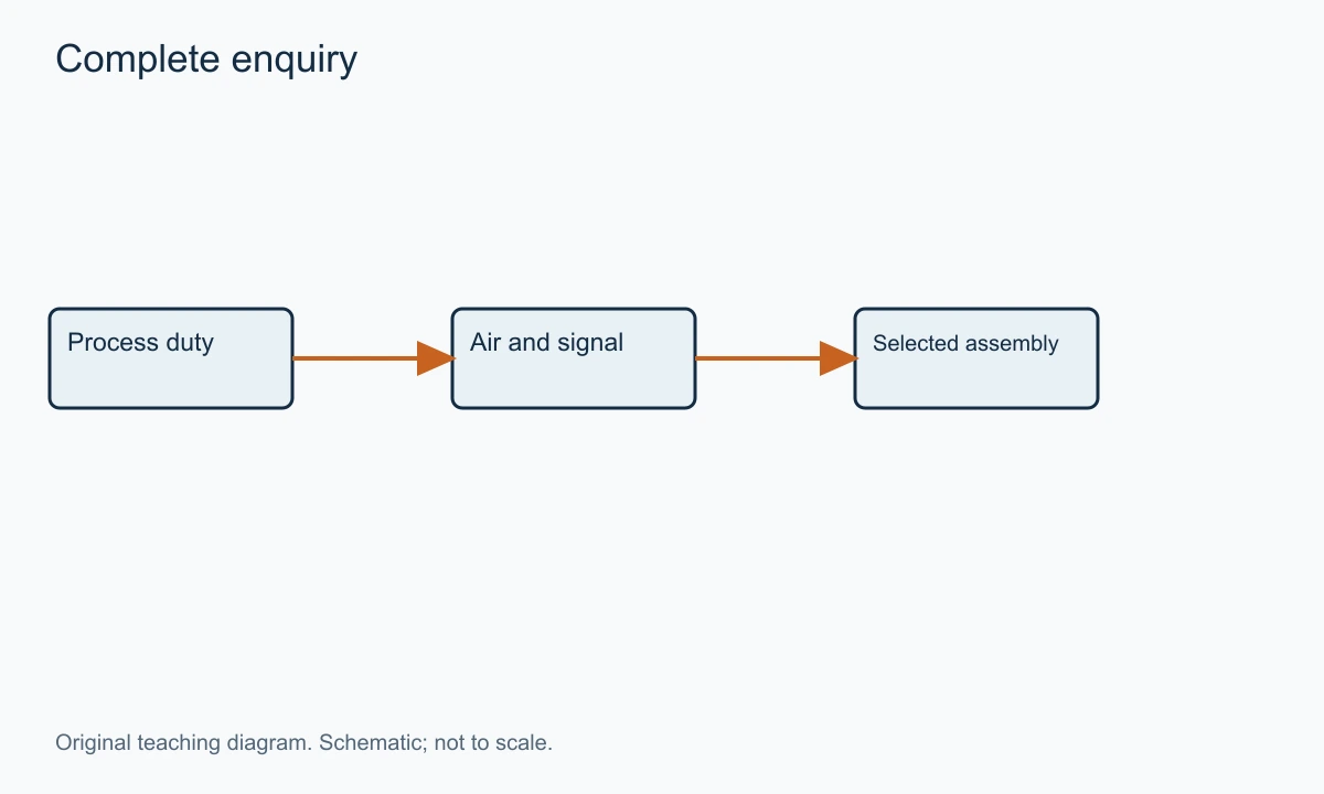
Add the available instrument air at the assembly, control signal, required movement time, environmental conditions and defined failure events. For a replacement, include the selected dimensions, current configuration and observed problem. A photograph helps identify components but does not supply the missing duty.
The mechanical interface includes connection standard, available length, orientation, support and service access. The actuator and positioner need room for maintenance as well as normal operation. Include insulation and ambient temperature where they affect the accessories.
Use the VantaValve quotation page with a process datasheet and pneumatic schematic where available. The resulting proposal should identify the complete assembly and state how its process, force and response requirements have been addressed.
FAQs on Pneumatic Control Valves
These questions resolve distinctions that remain after the process and air paths have been separated.
Is a pneumatic control valve the same as a solenoid valve?
No. A solenoid can switch a fluid or an actuator-air path. A pneumatic process control valve uses an air-driven actuator to regulate a process passage. A solenoid may be one accessory within that assembly without providing its continuous positioning function.
Does 50% command mean 50% flow?
Not generally. Command may correspond to a requested position, while flow depends on the trim characteristic and available differential. The installed system changes that relationship. Use a flow measurement or an appropriate sizing model rather than treat position as a flow meter.
Can increasing supply pressure solve slow movement?
Only if the selected assembly permits the pressure and insufficient pressure is actually the cause. Restricted delivery, exhaust limitations, friction or configuration can produce similar symptoms. Raising pressure without identifying the limit can overload equipment or leave the real problem unresolved.
Does a smart positioner remove the need for maintenance?
No. It can provide positioning and useful diagnostic information, but seats, packing, guides, air quality and mechanical connections still require attention appropriate to the service. Interpret diagnostics in terms of the variable and component actually measured.
Conclusion
A pneumatic control valve combines a process restriction, an air-driven actuator and a positioning or switching arrangement. Select the trim for the fluid and operating range, the actuator for the loaded movement, and the accessories for the required command and failure response.
A complete enquiry keeps process conditions, air supply and signal requirements separate but connected. That makes it possible to assess the whole assembly, rather than ask one strong actuator or advanced positioner to compensate for an unsuitable valve.
Need a valve for your application?
Send your valve type, operating conditions and quantity. Our team can help review the options for your inquiry.
Request a Quote →