Steam Pressure Reducing Valve: Size the Duty and Design the Station
Steam Pressure Reducing Valve: Size the Duty and Design the Station
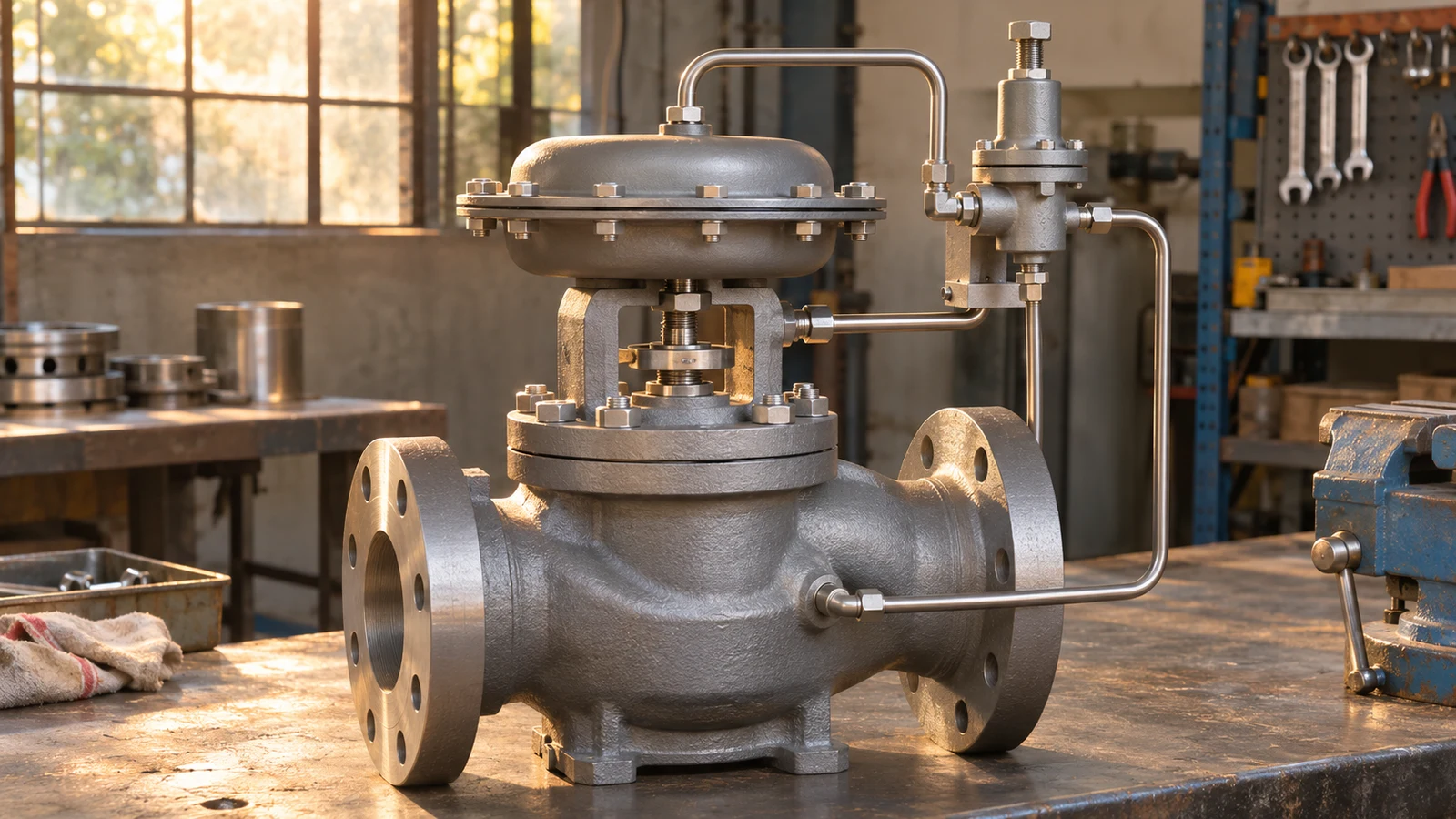
A steam pressure reducing valve regulates a lower downstream pressure by changing the passage from a higher-pressure steam supply. It is part of a station: drainage, steam condition, pressure sensing, isolation, pipe sizing and downstream protection can determine whether the selected regulator performs as intended.
Start with steam mass flow and the paired inlet and outlet conditions at minimum, normal and maximum demand. Pipe size alone is not a capacity specification. The maximum warm-up load can differ greatly from normal production, while a valve selected only for the largest load may regulate poorly during the many hours at low demand.
A successful selection therefore answers two questions together: which regulating assembly suits the load, and which station arrangement allows it to sense and control the intended pressure? Treating the valve as an isolated catalogue item leaves much of the actual duty unexplained.
What the Regulator Controls
A reducing valve senses downstream pressure and adjusts the inflow. When demand increases and the sensed pressure falls, the mechanism moves toward a larger opening. As pressure recovers or demand stops, it reduces the passage. The source must still provide enough pressure and mass flow for the required duty.
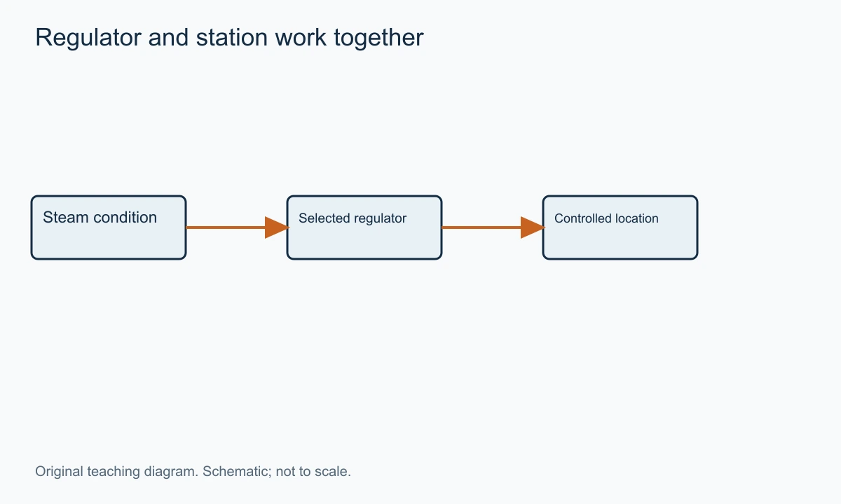
In saturated-steam systems, pressure and saturation temperature are related. Controlling pressure can therefore help establish a suitable heating condition where the steam remains at or near the intended state. This does not mean that a pressure reducer independently controls every downstream temperature regardless of superheat, heat transfer and condensate behaviour.
The regulator also dissipates pressure energy through throttling. It is not a turbine extracting useful shaft work. In an idealised steady throttling analysis with negligible heat transfer and kinetic-energy change between the chosen endpoints, enthalpy remains approximately constant. The downstream temperature must be determined from pressure and enthalpy, rather than assumed to fall along the saturation curve automatically.
That distinction matters when the inlet steam is dry or superheated. A lower pressure does not guarantee a saturated outlet. The selected assessment should identify the fluid state relevant to the process and trim. A pressure setting alone cannot establish the downstream steam quality.
The VantaValve control valve category is a starting point for discussing the required regulating function. A steam enquiry should include the full operating envelope so a self-acting or externally controlled assembly can be evaluated appropriately.
Direct-Acting and Pilot-Operated Steam Regulators
A direct-acting regulator uses downstream pressure acting on a bellows, diaphragm or another sensing arrangement to oppose the loading force and move the restriction. Its response depends on that mechanical balance. The pressure change needed as demand varies is part of the selection, not a defect to ignore after purchase.
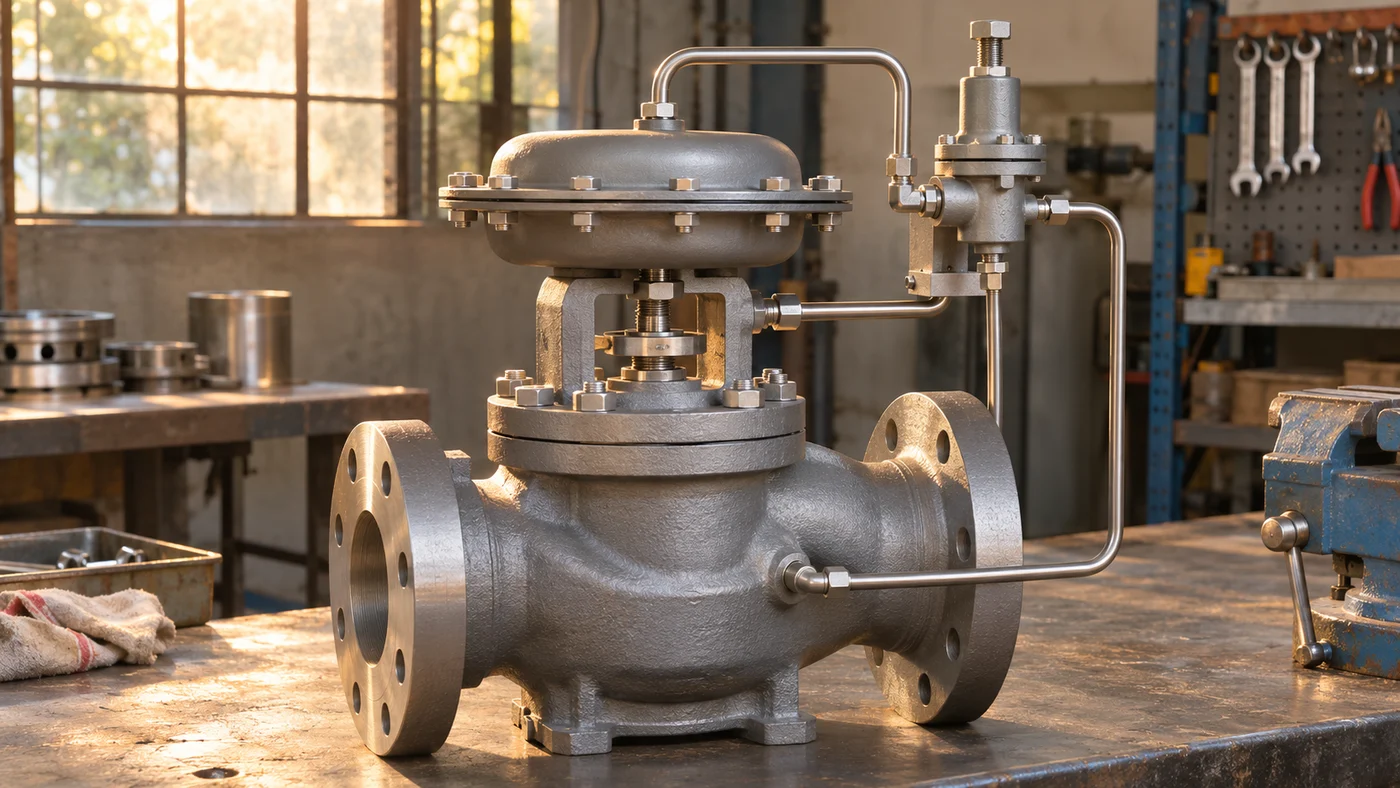
A pilot-operated regulator uses a smaller pilot to control the force moving a larger main valve. This can offer useful pressure control over a different capacity and load range. It also introduces passages and sensing arrangements that need the steam condition and maintenance described for the selected design.
Spirax Sarco's self-acting pressure-control tutorial distinguishes these families and explains why oversizing and steam condition matter. Its product-specific recommendations should be read in their stated context. The transferable selection task is to match regulation and capacity to the actual range of demand.
An externally controlled pneumatic or electric valve provides another option where remote setpoints, integration or a different control strategy are required. It adds a transmitter, controller and actuator arrangement rather than relying solely on a self-acting force balance. The complete loop then needs evaluation.
The most complex arrangement is not automatically the best. A moderate steady load with a compatible pressure tolerance may be served by a simpler construction. A variable process with a narrow pressure band can justify a different regulating system. Start from the required behaviour rather than from the number of accessories.
Describe Startup, Normal and Minimum Loads Separately
Steam used to warm cold pipework and equipment can create a startup load unlike the steady production load. The metal and process inventory absorb heat, and condensate forms as that warming occurs. The station needs to handle the approved startup sequence as well as the normal process condition.
A maximum mass-flow number without a duration or operating condition can be ambiguous. It may represent a brief warm-up demand, a sustained production case or a future allowance. Those conditions can lead to different selections. An unnecessarily large allowance can make the valve operate near its seat during most actual production.
At minimum demand, the regulating element needs a useful operating region and an acceptable pressure response. A valve capable of the maximum load may still have difficulty maintaining the required pressure at the smallest load. The relevant turndown belongs to the selected assembly and the complete system, not a generic family claim.
Prepare a duty table with the inlet pressure available at each load, the required downstream pressure and the mass flow. The upstream header pressure may fall during a high plant demand, so maximum flow and maximum inlet pressure should not be assumed to occur together.
| Illustrative condition | Steam mass flow | Inlet condition to provide | Downstream requirement to provide |
|---|---|---|---|
| Warm-up | Project-specific peak and duration | Available pressure and state during startup | Approved warm-up pressure and sequence |
| Normal production | Sustained operating mass flow | Normal inlet range | Required pressure and tolerance |
| Minimum load | Lowest sustained demand | Corresponding inlet range | Permitted regulation and no-load behaviour |
The table is a briefing structure, not a capacity recommendation. It exposes the missing paired conditions before a supplier is asked to select a nominal size.
Gauge Pressure, Absolute Pressure and the Reduction Ratio
A gauge pressure is measured relative to the local atmosphere. Absolute pressure includes that reference pressure. Steam-property and compressible-flow calculations require the correct basis, so the data should identify barg, bara, psig or psia explicitly.
For an illustrative calculation, take atmospheric pressure as 1 bar. A reduction from 10 barg to 3 barg then corresponds approximately to 11 bara upstream and 4 bara downstream. The absolute outlet-to-inlet ratio is 4/11, approximately 0.364. Dividing 3 by 10 would produce a different and physically inappropriate ratio for that purpose.
The example does not establish the selected valve's choked-flow limit. Compressible-flow sizing depends on the actual construction and applicable coefficients. A universal pressure-ratio cutoff should not be substituted for the manufacturer's sizing information.
The local pressure at the regulator inlet also matters. Loss through the upstream pipe, separator, strainer and isolator can reduce the pressure available at high flow. A remote boiler gauge may therefore overstate the pressure actually reaching the regulating valve.
State pressure locations as well as units. “10 bar supply” is less useful than “minimum 10 barg at the regulator inlet at the maximum sustained mass flow,” if that is what the process can actually provide. Precise conditions reduce ambiguity more than extra decimal places.
Why the Downstream Pipe Can Need a Different Size
Steam specific volume changes with pressure and state. A given mass flow can occupy a larger volume downstream of the reduction. The pipe therefore needs evaluation at its own condition, rather than automatically following the regulator's connection size.
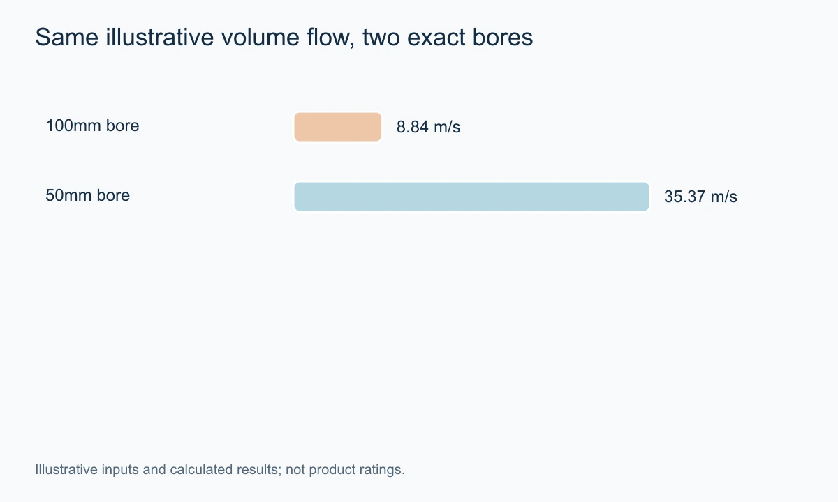
Consider an illustrative downstream mass flow of 500 kg/h and an assumed specific volume of 0.50m³/kg. These inputs give 250 m³/h, or approximately 0.06944 m³/s, at the downstream condition. The assumed specific volume is an example input, not a steam-table value claimed for a stated pressure.
For an idealised circular bore of exactly 100mm, area is approximately 0.007854m² and mean velocity is about 8.84 m/s. For an exactly 50mm bore, area is about 0.001963m² and mean velocity about 35.37 m/s. Halving diameter makes the area one quarter, so the calculated velocity becomes four times as large at the same volume flow.
Actual pipe internal diameters depend on the selected pipe and wall thickness. The acceptable velocity and pressure loss require the project's service and sizing criteria. The example explains the geometry; it does not prescribe a DN 100 outlet or a universal velocity limit.
A regulator can consequently be smaller than its adjacent pipework while still providing the required capacity. Reducers and expanders form part of the selected arrangement. Their locations and sensing effects should follow the actual station design rather than be added by appearance after the valve is chosen.
Dry Steam, Separation and Drainage
Condensate can collect in a steam line as heat is lost or cold equipment is warmed. Entrained liquid and accumulated condensate can change the service seen by the regulator. A pressure-control problem may therefore begin with steam condition and drainage rather than with the setting mechanism.
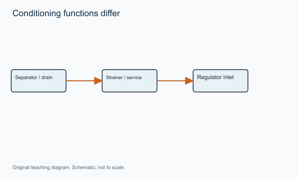
A separator removes entrained liquid through its selected mechanism and requires a suitable drainage arrangement. A strainer intercepts specified debris. They perform different tasks; one should not be substituted for the other because both can be installed upstream of the regulator.
A blocked or unsuitable drain can leave a separator unable to perform as intended. The trap and discharge arrangement must suit the differential and condensate conditions. The station should show where condensate goes, not simply place a trap symbol beneath the steam pipe and leave the destination unexplained.
Strainer orientation and drainage details depend on the selected equipment and service. A liquid-service habit can create an unwanted condensate pocket in steam service. Use the actual steam installation instructions rather than copying the orientation of another medium's sketch.
Spirax Sarco's pressure-control application guidance discusses the importance of clean, dry steam for pilot-operated controls. The practical implication is to review the complete upstream conditioning and drain path, not to assume a new regulator can tolerate an unresolved wet-steam arrangement.
Sensing Location and the Pressure Actually Controlled
An internal sensing arrangement responds to pressure at the point designed into the valve. An external sensing pipe can communicate pressure from a selected downstream location. The location affects what the regulator attempts to maintain.
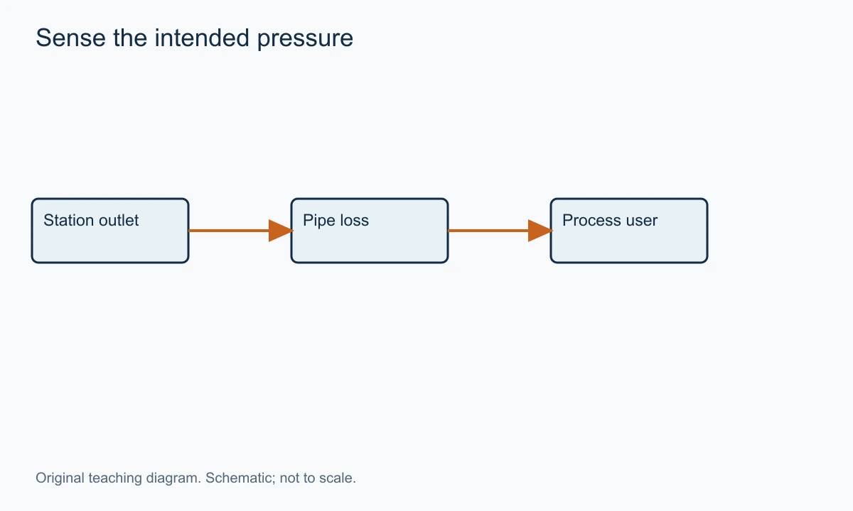
If the process user is separated from the regulator by a pipe with meaningful pressure loss, a correct regulator-outlet pressure can coexist with low pressure at the user. The discrepancy is a system pressure distribution, not necessarily an incorrect spring setting. State the location where the pressure tolerance applies.
External sensing needs a defined arrangement. A tap close to a disturbed flow region can communicate a condition different from the intended stable pressure. The selected manufacturer's recommended location and pipe details should guide the actual installation; a universal straight-length number would be misleading across different products.
The sensing line itself can be restricted, damaged or arranged in a way that changes its response. Its condition belongs in troubleshooting. A regulator cannot respond correctly to a pressure it does not receive as intended.
Remote sensing also does not remove downstream pipe loss from the system. The regulator may compensate within its capacity, but the required inlet differential, flow and stability still have to be available. The sensing location changes the controlled variable's location, not the energy balance.
Series and Parallel Regulators Solve Different Problems
Regulators in series divide the reduction into stages. This can be useful when the selected duty requires a staged pressure drop or another construction-specific benefit. Each stage needs sizing for the actual intermediate condition, including the mass flow and fluid state.
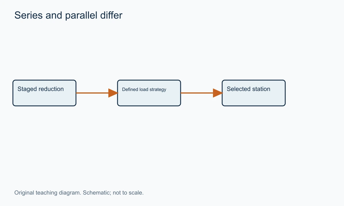
Parallel regulators divide or sequence the load. A smaller assembly may serve low demand while another addresses higher demand under a defined arrangement. This is a different task from sharing one pressure reduction across two stages. Two valves on the same drawing do not establish which function is intended unless their connections and operating strategy are clear.
The intermediate pressure for series operation should not be chosen only as an arithmetic midpoint. It must leave suitable operating conditions for both stages over the inlet and load range. Pressure limits, capacity, state and protection between stages all remain relevant.
For parallel operation, setpoints and interaction matter. Two regulators trying to control the same pressure can share load unevenly or interact unless the selected arrangement addresses their behaviour. A staged load strategy should have a documented operating basis, not merely two valves with identical settings.
Spirax Sarco's pressure-reducing product area provides the manufacturer route to the applicable model data. Use the actual documentation for a proposed station rather than treating a generic series or parallel sketch as a complete design.
Downstream Protection and the Failed-Open Case
A reducing valve performs routine regulation. Downstream equipment may still need protection against an overpressure scenario. The required protective arrangement depends on the maximum credible upstream condition, downstream limits and applicable project requirements.
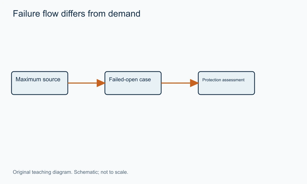
The failed-open regulator case can differ greatly from normal process demand. A protective device should not be selected merely from the normal mass flow if the defined failure can pass more steam. The relevant failure capacity and maximum source condition need to be established for the selected assembly.
Spirax Sarco's DP143/DP163 installation instructions discuss downstream safety-valve protection and the regulator's fully open capacity. This is a primary engineering reference for the distinction, not a substitute for the project's applicable protective-device sizing and discharge design.
Set pressure also needs coordination with the regulator's no-load behaviour and the protective device's reseating characteristics. Setting values too close without that assessment can create unwanted lifting or simmering. A blog example should not prescribe a protective setpoint for unknown equipment.
The discharge destination and piping are part of the protection function. A symbol pointing away from the line does not establish a suitable discharge arrangement. Keep the protective design and acceptance evidence as an explicit project scope alongside routine regulation.
Bypass and Isolation Arrangements
A bypass can support a defined operating or maintenance strategy, but it creates another route around the regulator. If that route is open, the regulator cannot control steam that passes through it. The bypass arrangement therefore needs the same attention to downstream pressure consequences as the main path.
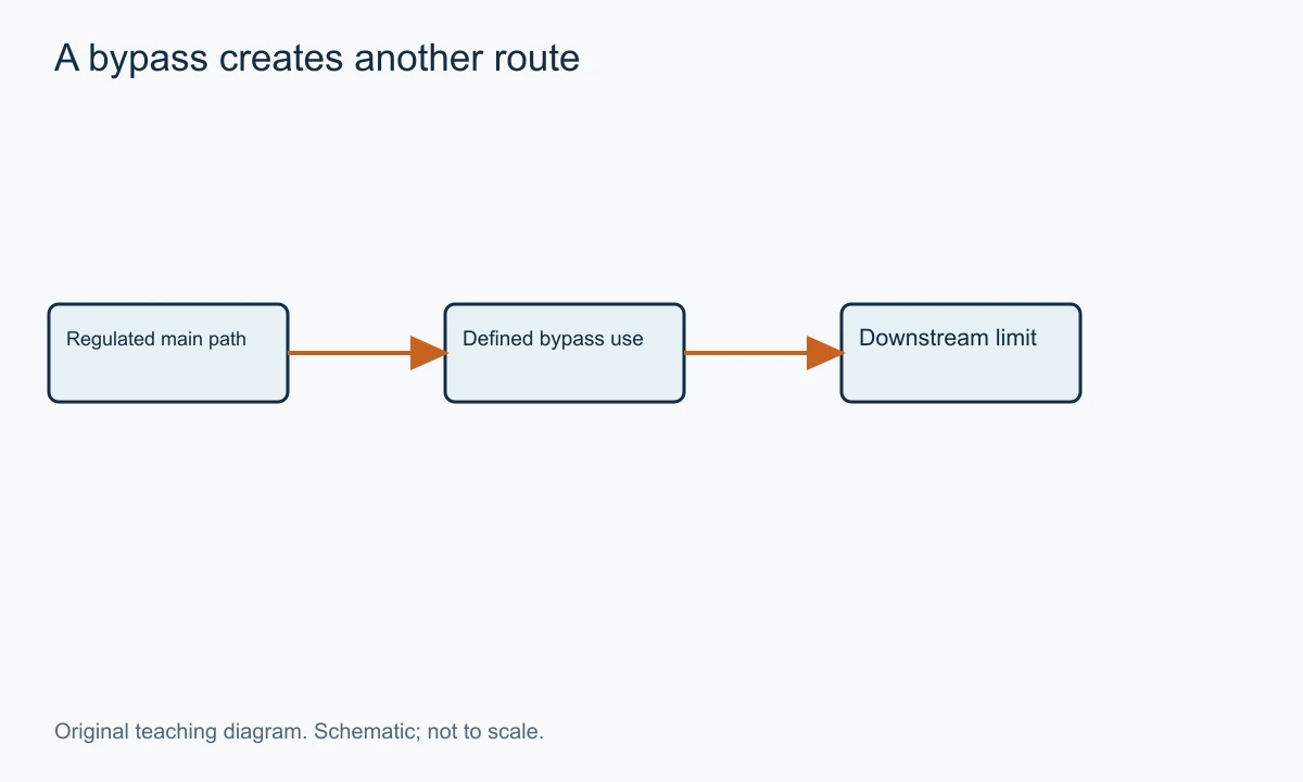
A manual bypass is not automatically a substitute pressure-reducing station. Its restriction does not regulate downstream pressure as demand changes. The approved operating method must account for that difference rather than assume a partly opened isolator behaves like a self-acting regulator.
Isolation valves support the planned maintenance condition. Their selected ratings, location and operation belong to the station design. The gate valve and globe valve families provide different possible functions, but the actual valve duty must be specified rather than assigned from habit.
Maintenance access should include the regulator's pilot, strainer, drain components and sensing line. A station can be hydraulically sensible yet difficult to service if all small components face a wall or sit beyond the platform. Show that access during the layout review.
Convert a Heat Requirement Into a Steam Mass-Flow Brief
A process heat balance can provide a useful first estimate of steam demand when direct flow data are unavailable. The relevant energy per kilogram is the enthalpy change between the steam supplied to the process and the condensate or other outlet condition included in the chosen boundary. It is not automatically one fixed latent-heat value for every installation.
For an illustrative process, assume a heat duty of one hundred and fifty kilowatts and a useful enthalpy release of 2,100 kilojoules per kilogram. Dividing gives approximately 0.07143 kilograms per second, or 257.1 kilograms per hour. The enthalpy value is an assumed example input, not a steam-table claim for a particular pressure.
If a warm-up condition requires three hundred kilowatts with the same assumed useful enthalpy release, the corresponding estimate is about 514.3 kilograms per hour. At a twenty-kilowatt minimum load, it is about 34.3 kilograms per hour. These cases span roughly fifteen to one in estimated mass flow.
That span does not by itself prove that one regulator can or cannot serve the process. It identifies a load-range question for the selected assembly. The high case may be brief, while the minimum can last for hours. A supplier should know both the numerical range and the time pattern before proposing a single valve or another load strategy.
Losses and other users need to be included within a clearly stated boundary. If a particular project calculation adds a quantified pipe heat loss, identify it separately. Do not hide an arbitrary percentage inside the steam demand and then add another unexplained sizing allowance at the supplier stage. Repeated allowances can produce a much larger selection than the actual requirement.
The process outlet condition also matters to the heat balance. Condensate leaving at a lower temperature can release sensible heat in addition to condensation energy, but the equipment and drainage arrangement must actually permit the assumed condition. A valve-sizing brief should not claim that energy contribution merely because it makes the calculated mass flow smaller.
A transparent brief can retain the heat duty and assumed enthalpy change alongside the resulting mass flow. That lets the process engineer replace the assumptions with verified values without rebuilding the whole selection discussion. It also keeps thermal design separate from the regulator's capacity calculation.
Understand What the Pilot Does to the Main Valve
In a pilot-operated arrangement, the small pilot does not normally carry the full process flow. It controls the pressure or force acting on the main operating mechanism through the selected internal passages. The main valve then changes the larger steam passage. This separates sensing and loading from the full-capacity restriction.
A small passage can therefore have a large effect on the main valve's behaviour. Debris or a restriction in the pilot circuit may change the pressure delivered to the operating chamber without blocking the main pipe. The exterior assembly can look unobstructed while the controlling path is impaired.
The direction of the response belongs to the design. A generic explanation should not assume that blocking any pilot passage always opens or always closes the main valve. Trace the selected schematic and its loading, supply and bleed paths before interpreting a symptom.
This is also why an accessory described as an override must be understood in context. A solenoid in a pilot circuit can alter the regulating action under a defined command. Its effect depends on where it is connected and what happens when power is removed. The word solenoid does not establish the entire failure response.
During a product comparison, request a clear functional description of the selected pilot arrangement. The useful questions are which pressure is sensed, what force opens and closes the main element, and which service conditions keep the small passages functional. Those explanations connect maintenance to the actual mechanism.
Mass Flow, Wetness and the Drainage Load Are Different Quantities
Steam mass flow includes the material crossing the selected boundary. If the inlet contains entrained liquid, some of that mass does not behave like dry vapour. The regulator and conditioning equipment then see a different physical service from an ideal dry-steam sizing case.
For an illustrative inlet of five hundred kilograms per hour with five percent of its mass present as entrained liquid, the liquid portion is twenty-five kilograms per hour. This arithmetic does not predict a real line's steam quality or a separator's collection efficiency. It shows that a seemingly small wetness percentage can create a meaningful liquid load that needs a defined path.
The drain system also handles condensate formed by heat loss and warm-up of the station. That load can occur at a different differential from normal operation. A trap selected only from a steady hot condition may not answer the complete startup case. The actual drain duty and discharge pressure belong in its selection.
A separator and a strainer do not perform the same separation. Liquid droplets and solid debris interact with different mechanisms. A clean strainer cannot establish dry steam, and a separator cannot be assumed to remove every particle that can affect a pilot passage.
The drainage route should therefore be visible on the station record. Identify the receiving condensate system, its pressure range and any elevation or other restriction relevant to the selected arrangement. A line ending at a drain symbol can conceal the boundary condition that determines whether liquid can actually leave.
Evaluate a Heat-Exchanger Demand Change
Imagine a station serving a batch heat exchanger. At the start of a batch, cold equipment and product require a high heat input. Later, the process approaches temperature and the demand falls. At the end, the heating control can reduce or stop the steam draw. The regulator experiences a sequence rather than one steady flow.
During the high-demand period, the minimum available source pressure can govern capacity. During the low-demand period, the selected regulator must remain useful near its minimum operating region. At no demand, its closing and no-load behaviour become relevant to the downstream pressure limit.
An oversized main regulator can make a low-demand problem more noticeable because a small movement admits a relatively large amount compared with the required load. A smaller low-load path or another selected control arrangement may be considered, but only after the actual operating cases have been established. Adding another regulator without a defined strategy can introduce interaction rather than solve it.
The station also interfaces with condensate removal from the heat exchanger. Pressure within the steam space can change as the control action reduces supply. The condensate system has its own return pressure and elevation. A pressure-reducing valve upstream cannot independently solve every drainage limitation at the user.
The useful supplier brief therefore includes the batch sequence and connected equipment, not only the peak mass flow. A short load history can show why a station that works well during warm-up behaves differently near the end of the batch. The selected solution should address the process sequence rather than only the loudest symptom.
A Staging Calculation Is a Starting Point, Not a Station Design
Equal pressure ratios can be explored with absolute pressures, but the algebra should not be mistaken for a product recommendation. Suppose an illustrative source is ten bar absolute and the final requirement is three bar absolute. An equal-ratio intermediate pressure would be the square root of thirty, about 5.48 bar absolute.
The resulting outlet-to-inlet ratio for each idealised stage is approximately 0.548. Multiplying the two ratios gives the overall ratio of 0.3. The calculation shows why using gauge pressures in the same ratio can produce another answer; the physical reference matters.
The selected intermediate pressure may differ. Available products, steam state, capacity, noise, minimum differential and the operating range can make another distribution appropriate. Each stage's actual sizing and limits should determine whether the proposed arrangement works.
The interstage pipe also needs a condition at no load. Heat loss can form condensate while the station is idle, and that liquid needs the intended drainage route before demand increases again. The fact that both regulators are correctly sized for steady mass flow does not establish that the connecting pipe remains suitable through the full cycle.
State the chosen intermediate condition and its basis in the station record. That lets later changes be evaluated. Replacing one stage with another size or trim can change the balance, even if both end pressures remain written on the P&ID.
Use the Selected Manual to Distinguish Range From Rating
A manufacturer's assembly can have an adjustable downstream range, a maximum upstream steam condition, a pressure-boundary envelope and connection-dependent limits. These are separate constraints. A broad range in one note does not override another limit in the same document.
The Spirax Sarco DP27 installation manual, for example, distinguishes the standard downstream adjustment range from the narrower range of a DP27Y version. It also provides separate limits for variants and connections. This is evidence of configuration-specific selection, not a set of ratings to combine into one generic steam regulator.
For an enquiry near a range boundary, identify the exact proposed version and selected loading arrangement. A valve body with the right nominal size can still contain the wrong regulating range for the intended low pressure. Changing an adjustment is not the same as changing the approved assembly configuration.
The model suffix can also identify an additional function or another medium-related construction. Preserve it in the specification and spares record. Omitting suffixes because the exterior looks similar can remove the very detail that distinguishes the required performance.
Use the manual as the applicable product reference, while retaining the process cases alongside it. One describes what the selected equipment permits; the other describes what the process asks it to do. Suitability is the match between them.
Read a Station Pressure Trend at Four Locations
For a difficult operating issue, distinguish the upstream header, regulator inlet, regulator outlet and actual user. These locations can have different pressures under flow. A reading at one should not be used as if it represents all four.
If the header remains steady while the regulator inlet falls during peak demand, the upstream connecting path deserves attention. A strainer, isolator or pipe loss can consume pressure before the main valve. The regulator cannot recover pressure already lost upstream.
If the regulator outlet meets its target while the user is low, examine the downstream distribution and the sensing location. The valve may be performing its local task while the specified process location remains unsatisfied. The solution should follow the actual pressure requirement rather than treat the local gauge as the sole acceptance point.
If the user pressure rises with no demand, record the time behaviour and any bypass condition. The regulator's closing response, seat or pilot condition, and another connected supply path can lead to different explanations. The actual station schematic helps identify which mechanisms are possible.
The temperature and load history add context. A cold startup, a hot steady run and a long idle period can reveal different limits. A trend labelled with those operating states is much more useful than a list of disconnected maximum and minimum readings.
Keep the Scope of a Valve Quote and a Station Quote Clear
A regulator-only quotation can be entirely legitimate while leaving the separator, strainer, drains, sensing pipe, isolation and protective functions outside its scope. The risk is not the limited scope itself but an assumption that the entire station is included because the main valve is supplied.
A station proposal should identify those components and the responsibilities for their sizing and installation. It should also state the connection and documentation boundaries. The process owner can then see which pressure, drainage and protective questions have actually been addressed.
For a replacement, distinguish reusable station items from items whose duty changes with the new regulator. A different failed-open capacity can affect the protection assessment. Another body size can change transitions, sensing geometry or service access. A dimensionally convenient replacement should not bypass those functional checks.
The most useful comparison is therefore a complete scope list linked to the same process cases. A cheaper quote may reflect a smaller scope rather than a more economical way to meet the full requirement. Resolve that difference before comparing the final commercial values.
Diagnose Pressure Problems by Operating Condition
A low downstream pressure at high demand can indicate inadequate inlet pressure, insufficient selected capacity, an upstream restriction or another station problem. Record the pressure at the regulator inlet under the failing condition before assuming the spring needs adjustment.
Pressure that rises after demand stops needs a different investigation. The regulator's no-load behaviour, seat condition, pilot function and any bypass path can be relevant. The timing and magnitude of the rise help distinguish a settling response from continued admission.
Oscillation can involve sensing, load changes, oversizing or interacting controls. Compare the pressure trend with demand and valve behaviour. Repeated adjustment without recording the conditions can remove the evidence needed to separate those mechanisms.
Noise or vibration can arise from severe flow conditions, mechanical movement or condensate-related events. Sound alone cannot identify the cause. Include mass flow, pressures, temperature, drainage observations and the point in the operating sequence when it occurs.
A change in production can also invalidate the original load range. A regulator sized for several users may spend most of its time on one small user after a plant modification. The appropriate response may involve a new load strategy rather than replacing the same worn component indefinitely.
A Warm-Up Estimate Separates Total Energy From Peak Rate
The same equipment can require a different peak steam rate depending on the permitted warming time. Consider an illustrative one-hundred-kilogram metal component with an assumed constant heat capacity of 0.5 kilojoules per kilogram-kelvin and a one-hundred-and-fifty-kelvin temperature rise. The idealised sensible heat requirement is 7,500 kilojoules.
With the earlier assumed useful steam enthalpy release of 2,100 kilojoules per kilogram, that heat corresponds to about 3.57 kilograms of steam. This is a simplified energy estimate that neglects losses and other heated material. It is not the total startup load of an actual station.
Delivering that energy over fifteen minutes gives an average steam rate of about 14.3 kilograms per hour. Delivering it over five minutes gives about 42.9 kilograms per hour. The idealised total steam mass is unchanged, while the average rate during the warming interval is three times as large.
This explains why a startup brief needs a duration. A short warming target can create a much higher rate than a longer controlled sequence, even before production begins. The actual permissible sequence also depends on equipment and process constraints, so the calculation does not justify choosing the fastest warming time.
Include the heated pipe, equipment and process inventory within a clear boundary. If another calculation already includes part of that inventory, do not count it again as a station allowance. A transparent energy basis helps prevent repeated margins from producing an unnecessarily large regulating valve.
A Self-Acting Steam Pilot Is Not Necessarily an Air Actuator
A steam pilot-operated regulator can use the process pressure through its selected passages to operate the main mechanism. It should not be assumed to require an instrument-air supply merely because a diaphragm chamber is visible. The energy and sensing paths belong to the actual construction.
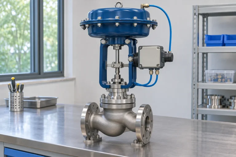
An externally controlled pneumatic process valve is different. It uses an air-driven actuator and a control arrangement that can include a transmitter, controller and positioner. Both can regulate a steam line, but they have different utilities, configuration and maintenance scope.
The visible diaphragm is therefore not enough to identify the system. Trace the connected medium and the manual's functional description. A small tube carrying sensed or operating steam pressure is not interchangeable with an instrument-air tube.
This distinction matters when a plant considers a replacement. A self-acting assembly may serve a local pressure task without the same external utilities, while an integrated control requirement may favour another arrangement. The choice should follow the desired process behaviour and available infrastructure, not the resemblance of two product photographs.
Pressure Regulation Can Interact With a Downstream Control Valve
A station may maintain a pressure header that supplies a separate temperature-control valve. When the temperature valve opens, demand rises and the pressure regulator responds. When it closes, the regulator sees a falling load. The two controls are connected through the same steam volume even if they measure different variables.
The selected pressure and temperature control arrangements should therefore be assessed as a system. A regulator sized for a steady load may encounter rapid demand changes from the downstream valve. A temperature valve selected assuming a constant inlet pressure may behave differently if the local header varies substantially.
The useful operating record relates both actions to the pressure and temperature trends. Oscillation in one trace does not prove which component caused it. The sequence of demand, pressure response and control movement helps identify whether the issue is capacity, sensing, tuning or another station condition.
A larger regulator is not an automatic remedy for interaction. It can change the gain and low-load operating region as well as increase capacity. Review the paired cases and actual response before changing the mechanical selection solely to suppress a symptom.
This is another reason to include downstream users in the station enquiry. The main valve's duty is shaped by how those users draw steam, not only by their combined nameplate maximum. The supplier needs that operating pattern to propose a defensible regulating arrangement.
A Pressure Regulator Does Not Guarantee Condensate Return
The pressure maintained at a steam header is not necessarily the pressure available inside every downstream user at every point in its control cycle. A temperature-control valve can reduce steam-space pressure as demand falls. The condensate return still has its own pressure and elevation.
For an illustrative condition, suppose a user steam space is at one bar gauge while the receiving condensate line is at two bar gauge. Ignoring elevation and other losses, there is no positive pressure difference to drive passive discharge from the lower-pressure space into the higher-pressure return. A larger flow passage alone cannot create that missing differential.
An upstream reducing station set to three bar does not resolve the example if a downstream control condition leaves the actual steam space at one bar. The pressures belong to different locations. The complete heating and condensate arrangement needs assessment for its actual operating cycle.
The example is a boundary explanation, not a drainage design or a prescribed repair. A suitable solution depends on the equipment, return system and selected components. Its value is to prevent a regulating valve from being blamed for every consequence of a pressure distribution it does not directly control.
Include the condensate return condition in a station discussion when it affects the user. A clear schematic and operating cases allow the pressure and drainage tasks to be assessed together without pretending they are one interchangeable valve function.
Cold Test Pressure Is Not a Steam Operating Rating
A selected manual can list a cold hydraulic test pressure above the normal operating envelope. That test establishes a defined inspection condition. It does not grant permission to operate continuously at the test pressure or at that pressure with hot steam.
Temperature, material, connections and internal components determine the operating limits. The presence of a higher test number in the same document should not be used to override those limits. A data table must be read by the role of each value, not by choosing the largest number.
For an enquiry, keep design, operating, differential and test conditions in separate fields. That prevents a pressure-boundary inspection requirement from being mistaken for a capacity or steam-service approval. The supplier can then identify which evidence addresses each part of the specification.
Main-Line and Pilot Filtration Can Have Different Jobs
A station can include a main-line strainer and a separate small filter or strainer associated with the selected pilot circuit. Their jobs follow the paths they protect. A clean main-line element does not prove that every small control passage is clear.
The selected parts list and manual should identify the elements that actually exist. Do not assume every pilot uses the same internal filtration or that an accessory shown for another model is included. The inspection scope follows the supplied assembly.
Pressure readings can help locate a restriction only when they are taken at relevant points and conditions. A blocked element that affects pilot response may not produce the same bulk-flow symptom as a heavily fouled main-line strainer. Trace the functional path before replacing the main regulator for a problem in an auxiliary passage.
Access and spares should cover those small components as well as the pressure body. They can be inexpensive relative to the main valve while still having a significant effect on its response. A complete station record makes that relationship visible without overstating the performance of any unspecified product.
Prepare a Station Enquiry That Can Be Sized
Provide minimum and maximum upstream pressures at the station, the required downstream pressure at a defined location, and steam mass flow for startup, minimum and normal operation. State whether the inlet is saturated, wet or superheated to the extent established by the process data.
Include downstream equipment pressure limits, the defined protective scope and any existing regulator, bypass or control-valve arrangement. A simple schematic should show the separator, strainer, drains, sensing point and discharge destinations as applicable. Do not assume those functions are included in a valve-only quotation.
Add connections, materials, available space, insulation, access and documentation requirements. For a replacement, give the actual selected model, current operating problem and any duty changes. The valve documentation guide helps retain that record.
Use the VantaValve quotation page with the paired operating cases. A useful proposal identifies the regulator, station scope and relevant sizing assumptions, rather than return a pipe-size match with an unexplained pressure ratio.
FAQs on Steam Pressure Reducing Valves
These questions address distinctions that can remain after the load and station arrangement are understood.
Can a water pressure reducer be used for steam?
Only a selected product explicitly suitable for the actual steam pressure, temperature and construction duty should be considered. Similar external shape or connection size does not establish steam suitability. Body, trim, seals and sensing arrangement all matter.
Does reducing pressure always make saturated steam at the outlet?
No. Throttling changes pressure without necessarily placing the outlet on the saturation line. Determine the downstream state from the actual inlet state and the applicable thermodynamic assessment. Pressure alone does not establish steam quality.
Should the regulator match the main pipe size?
Not automatically. Capacity is selected from mass flow and operating conditions, while adjacent pipe sizes are assessed at their own volume flow and loss requirements. A smaller regulator with appropriate transitions can be a valid selected arrangement.
Is a bypass a backup automatic regulator?
A plain manual bypass does not provide the same feedback regulation. Its use needs a defined operating strategy and assessment of downstream consequences. Another automatic station is a different scope from a bypass line containing an isolator.
Conclusion
Select a steam pressure reducing valve from paired pressure and mass-flow cases, then design the station that allows it to regulate the intended location. Steam condition, drainage, sensing and downstream protection are functional parts of that result.
For a useful supplier discussion, provide the load range, fluid state and station schematic together. That gives the proposal a basis in the actual process and keeps a nominal-size valve purchase from standing in for a complete pressure-reduction arrangement.
Need a valve for your application?
Send your valve type, operating conditions and quantity. Our team can help review the options for your inquiry.
Request a Quote →