Check Valve Symbol: Read Direction, Function and Drawing Context
Check Valve Symbol: Read Direction, Function and Drawing Context
A check valve symbol identifies a non-return function: the intended forward flow can pass, while reverse flow is resisted. To read it reliably, first establish the drawing's symbol convention, then identify the permitted direction and the connected equipment. A symbol is a functional description, not a miniature drawing of the valve's actual internal mechanism.
The same non-return task can be drawn differently on a process P&ID and a hydraulic or pneumatic circuit. A process drawing may use a directional closure mark, while a fluid-power drawing may show a ball or poppet against a seat, with a spring or pilot connection where relevant. The legend and the applicable drawing system determine what the marks mean.
This guide uses original teaching diagrams, not reproductions of a standards catalogue. They explain how to reason from a symbol to the function and then to the documents needed for specification. A project drawing's approved legend remains the controlling reference for that project.
Begin With the Drawing Family
A process P&ID shows functional relationships among piping, equipment and instrumentation. It is not normally a physical installation drawing. A hydraulic or pneumatic circuit uses another visual language to describe the paths and operating functions within a fluid-power system. Both may contain check valves, but a familiar shape from one should not be imposed on the other.
ISO 10628-2 addresses graphical symbols for diagrams in chemical and petrochemical applications. ISO 1219-1 addresses symbols for fluid-power systems and components. These scopes explain why a search for one universal check-valve image can return several valid-looking conventions with different surrounding detail.
ISA's instrumentation and control symbols work concerns the identification and depiction of measurement and control functions. A reference to ISA on a drawing does not remove the need to read its valve legend, line conventions and project notes. Different parts of a drawing package can apply different standards and project conventions together.
Before interpreting an isolated crop, locate the drawing title, legend reference, revision and service. A symbol taken from a training slide may be adequate for identifying a function but insufficient for changing an installed system. The surrounding documentation supplies the conditions the cropped image leaves out.
What the Basic Non-Return Symbol Communicates
A basic check-valve mark communicates a preferred direction through the component. In a simplified ball-and-seat teaching sketch, pressure from the forward side can move the ball away from its seat. Pressure from the opposite side pushes it toward the seat. That physical explanation helps interpret the permitted path without relying on the page's left or right edge.
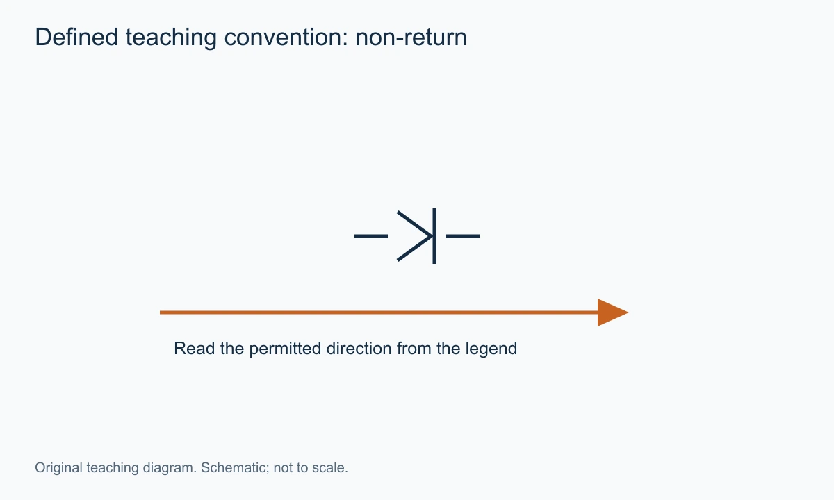
A directional mark in a process P&ID may communicate the same function without depicting a ball. It should not be interpreted as proof that the installed valve is a ball check. The drafter is representing the non-return job, not necessarily the closure shape.
The symbol can be rotated or mirrored to follow the pipe route. A rightward flow in one teaching example becomes upward, downward or leftward when the same function is placed elsewhere. The orientation of the page is therefore a poor memory aid. Trace the permitted path through the component itself.
A nearby flow arrow can help, but distinguish the arrow's job. It may indicate the intended process flow in the line rather than form part of the valve symbol. The check-valve orientation should agree with the required function. If they conflict, record the discrepancy for resolution rather than assume one can be silently reversed.
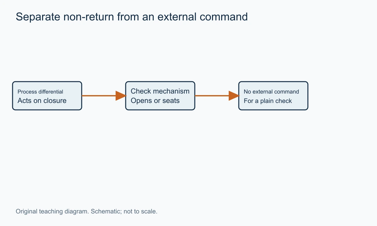
A check valve is automatic in the sense that the process differential and its internal forces operate it. A plain non-return symbol does not imply an electrical command, position feedback or an external actuator. Those functions need additional representation or documentation when the drawing system includes them.
The VantaValve check valve category contains the relevant product family. A product selection follows the functional identification; it cannot be completed from the symbol alone.
A Five-Step Reading Method
Read the mark as part of a connected system. The following sequence gives an interpretable result and also makes clear what remains unknown.
- Identify the drawing family and its approved legend. Determine whether the mark belongs to a process P&ID, a fluid-power circuit or another document.
- Trace the two process connections. Establish which way the depicted closure permits flow under its normal non-return function.
- Read the equipment and line context. Locate the pump, vessel, header, actuator or other connected component that explains the reason for the check.
- Read the tag and associated references. Use the project's abbreviation rules, line list, valve schedule and datasheet rather than guessing from letters.
- Separate the functional conclusion from the hardware specification. State what the valve is intended to do, then identify the missing type, rating and operating data.
Describe the permitted path in a sentence that names the connected equipment. For example: “This check permits flow from the pump branch into the common header and resists return from the header toward the stopped pump.” That statement is more useful than “the triangle points right,” because it ties direction to equipment that will remain identifiable if the drawing is rearranged.
Spring-Loaded Check Valve Symbols
A spring mark indicates that a spring contributes to the closure behaviour in the depicted construction. It adds information to the basic non-return function. It does not specify the spring material, preload, cracking pressure or permitted installation positions unless the drawing includes those details elsewhere.
The spring is particularly easy to overread. A small zigzag line can appear precise, encouraging the assumption that the valve closes at a known differential. In reality, the initial opening condition depends on the assembled mechanism and stated test conditions. A spring symbol identifies a force contribution, not its calibrated value.
The existing cracking pressure guide explains the distinction between initial opening, resealing and passing useful flow. For drawing interpretation, keep those terms separate. A note such as “0.2bar cracking” does not supply a pressure-loss curve at the required operating flow.
Nor does a spring symbol establish a universal failure position in the control-valve sense. A simple non-return valve reacts to the process differential and internal forces. It is not normally receiving a command to choose an open or closed state. A mechanically assisted closure and an actuated shutdown function are different descriptions.
A spring-loaded mark also does not prove that the product may be installed vertically downward. The guide, moving mass and manufacturer instructions can impose conditions. Read installation permissions from the selected valve documentation, not from the existence of the spring mark.
Pilot-Operated Checks: A Second Connection Changes the Task
A pilot-operated check valve adds a control connection that can influence the non-return function. In an appropriate hydraulic arrangement, pilot pressure can release the normally blocked direction so a held volume can discharge when commanded. That is a different job from a plain process check that responds only to its main-line conditions.
The pilot connection is therefore not an optional decoration. Trace where it comes from and under what circuit condition it receives pressure. A check symbol with an unexplained third line should prompt a closer look at the legend and circuit, rather than be treated as a three-way process valve.
A Parker hydraulic valve catalogue illustrates the use of pilot-operated check functions within its hydraulic product context. Its pilot relationships and ratings belong to its listed products. They should not be inferred for another component from a similar-looking symbol.
The circuit may need a specific relationship between pilot pressure, load pressure and the valve's internal areas. A symbol establishes the functional arrangement, but it normally cannot supply all the data needed to determine release under a load. The actual product information and circuit conditions are necessary.
This distinction prevents a serious procurement error: replacing a piloted holding function with a plain inline check of the same connection size. The latter may permit filling but provide no intended way to release the blocked side through the original pilot circuit. Equal ports do not mean equal function.
Check Valve, Isolation Valve and Flow Arrow: Three Different Meanings
A check valve resists reverse flow automatically. An isolation valve provides a deliberately operated barrier under its specified conditions. A flow arrow indicates direction. Those marks can appear beside one another, but none should be substituted for another merely because the line needs to stop flowing.
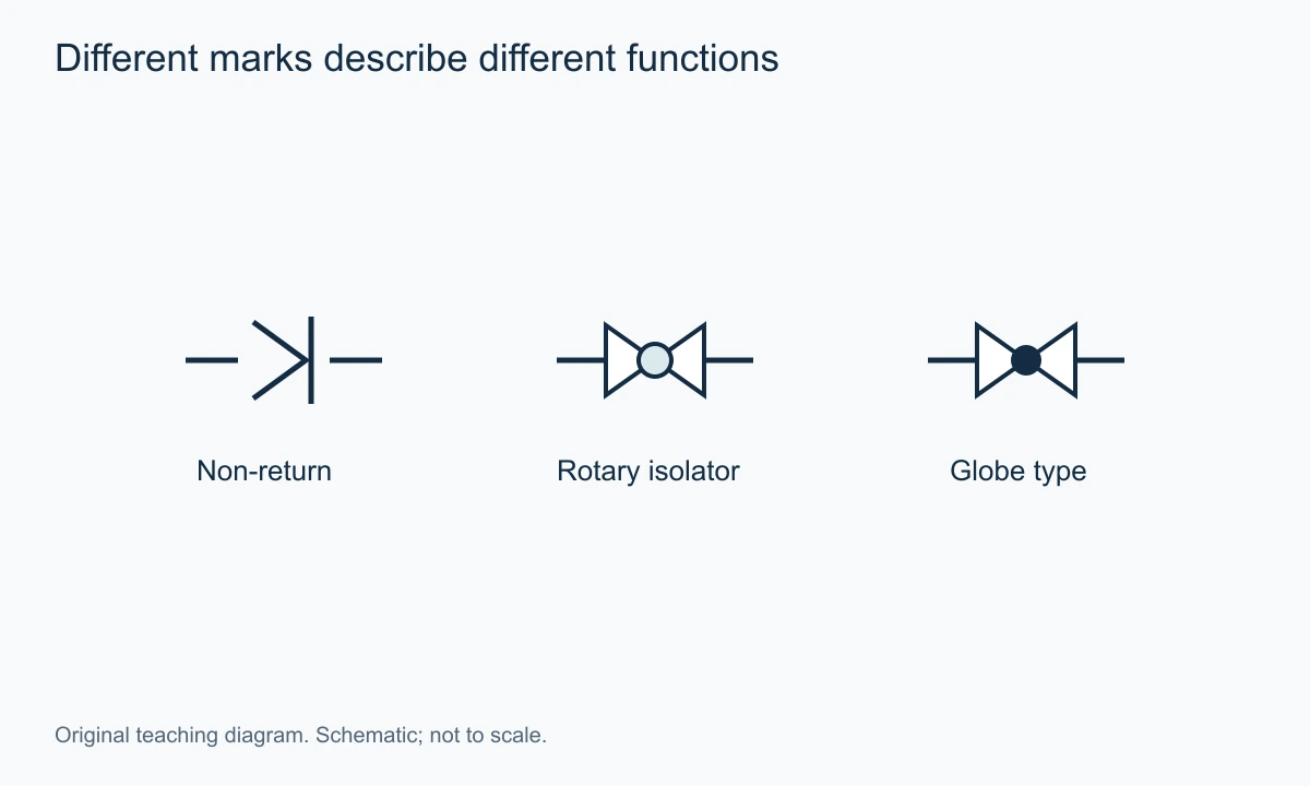
A plain arrow in a pipe is not a complete check-valve symbol. It often describes intended flow and contains no automatic closing function. Conversely, a check symbol can be drawn on a line without an additional flow arrow because its direction is already communicated by the convention.
A manually operated valve symbol identifies another function. Its operator or tag may distinguish a gate, ball or other construction. The existing gate-valve symbol guide addresses that family. Comparing it with a non-return mark helps show why the drawing must distinguish deliberate isolation from automatic resistance to reversal.
A pressure-relief or reducing function also differs from a check. All three can involve springs, seats and differential pressure, but they control different variables or paths. The number and location of connections, sensing lines and pressure notes help establish the intended function.
When a drawing crop is unclear, write down what the mark would need to accomplish in each interpretation. If one interpretation would prevent the required pump discharge or leave a required reverse path open, the surrounding circuit can expose the inconsistency. Use that reasoning to frame a question, not to overrule the approved drawing without review.
Reading a Pump-Discharge Example
Imagine a pump with suction from a storage tank and discharge into a pressurised header. A check symbol sits in the discharge branch. Its intended permitted direction is from the pump toward the header. When the pump stops, header pressure can otherwise drive liquid back through the branch.
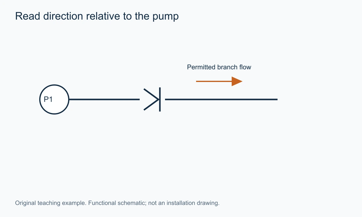
The P&ID establishes the function and its relationship to the equipment. It does not normally show the pipe's elevation, exact valve orientation or required straight lengths. Those conditions come from layout and manufacturer documentation. A symbol drawn horizontally on paper can represent a valve installed in a vertical pipe.
An isolation valve may appear beside the check so maintenance can be arranged under the project's requirements. That adjacency does not make the two functions redundant. One responds automatically to reversal; the other is deliberately operated to establish the intended isolated condition.
The drawing also does not prove that the chosen check closes with an acceptable transient. A non-return function can be correctly located while the selected mechanism still needs dynamic assessment. The existence of the symbol answers “what should happen,” while the selected product and system study address “how it happens.”
For installation detail, use the check-valve installation article. Keeping the document roles separate prevents a functional schematic from being treated as a complete field procedure.
Reading Parallel Pump Branches
With two pumps connected to a common header, each branch may have its own check. The permitted directions lead from each pump into the shared line. When one pump runs and the other stops, the stopped branch's check is intended to resist header flow back through that pump.
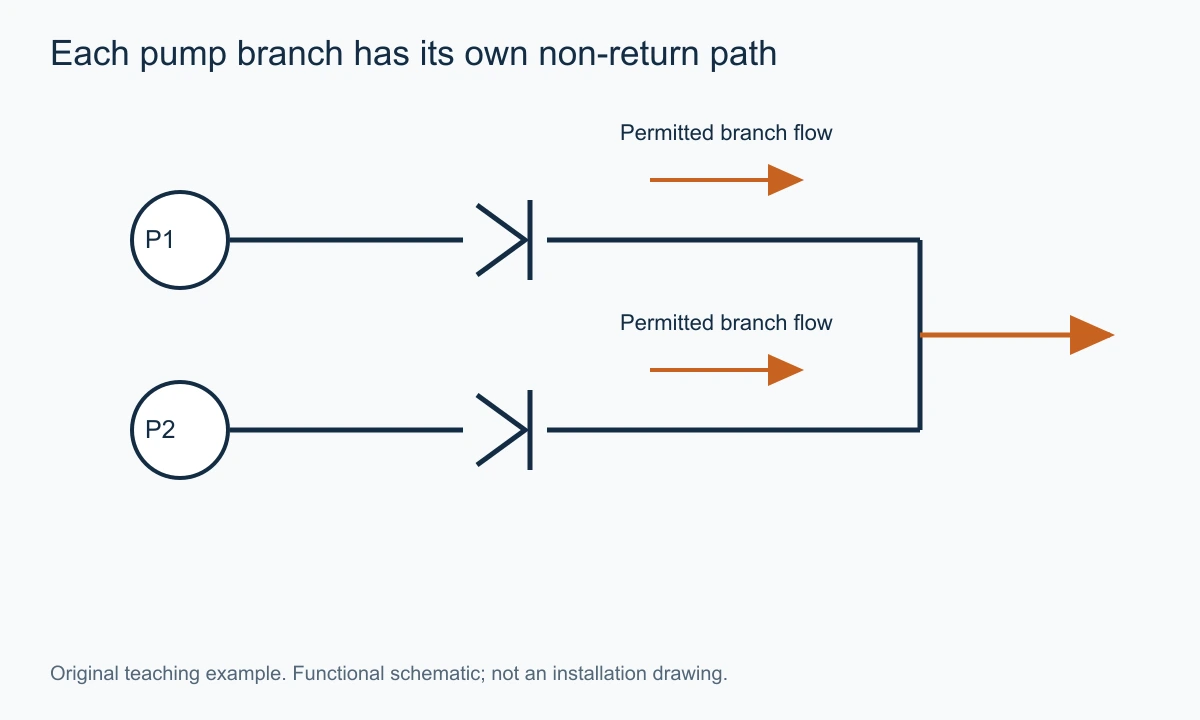
Trace the connections carefully at crossings. A crossing line is not necessarily a connection; a junction mark or the project's convention determines it. A mistaken junction can change the apparent reason for the check and lead to a wrong interpretation of which pump supplies which branch.
The branch identity also matters to specification. The check in one branch sees that branch's flow, not automatically the combined header flow. The drawing helps establish which duty belongs to the valve, while the flow balance supplies the numerical cases. A list of total plant flow without branch conditions can be insufficient for selection.
A bypass line creates another path that must be traced independently. A correctly oriented check on the main branch cannot prevent flow through a bypass that remains open. The functional conclusion must account for every connected route, rather than stop once a familiar non-return symbol is found.
This example shows the practical value of system reading. Identifying the component is only the beginning. The useful task is determining which reversal the arrangement is intended to resist and whether another depicted path changes that conclusion.
Foot Valves and Combined Functions
A foot valve is commonly a non-return assembly at a suction intake with a straining function. A drawing may represent the combination with a special mark or a check and strainer relationship, depending on the convention. The important reading is the two jobs: retain the intended liquid condition and limit entry of specified debris.
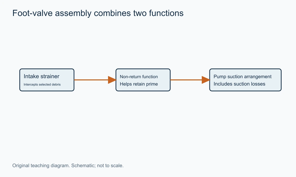
The presence of a strainer function does not identify its mesh, open area or clean and fouled pressure loss. Those properties affect the suction arrangement and must be specified separately. The symbol does not establish that the pump will have adequate inlet conditions.
A combined stop-check design adds another functional distinction. It may incorporate a way to prevent the closure element from lifting, while also providing a non-return action when the operating arrangement permits it. The selected construction's actual functions and procedure must be understood; a label cannot be assumed to mean that the valve can be forced open against every reverse condition.
Similarly, a dual-plate check is not a double-check backflow-prevention assembly. Two closure leaves within one valve are not equivalent to two independent check stages in series. If a drawing requires an approved assembly for a particular backflow-protection function, the required assembly specification must be followed.
Do not turn every combined name into a new invented symbol. Use the project's approved library or reference the function clearly in the schedule. Consistency is valuable because the person reading the drawing later should not have to infer an unfamiliar drafter's private convention.
What the Symbol Cannot Tell You
A basic non-return symbol normally leaves many procurement questions unresolved. It may not identify whether the mechanism is swing, lift, ball, dual-plate or axial. It may not provide the body material, seat material, connection, pressure class or dimensional envelope. That is a normal division of information across a drawing package.
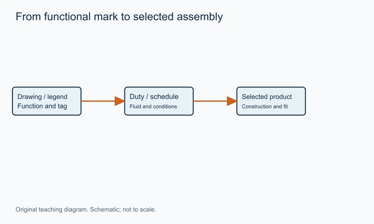
The valve schedule and datasheet connect the functional item to the hardware. The line class can constrain materials and connections. The operating description identifies the duty. The manufacturer's selected drawing and manual then provide product-specific movement, installation and maintenance information.
| Document | Question it helps answer |
|---|---|
| P&ID and legend | What function is connected where, and in which permitted direction? |
| Valve schedule | Which tagged item and specification apply? |
| Line list and piping class | What line service and mechanical requirements are assigned? |
| Process duty or datasheet | What fluid, flow, pressure and temperature must be handled? |
| Selected product data | What mechanism and performance does the proposed assembly provide? |
| Layout and installation documents | How is the assembly physically arranged and accessed? |
The table explains why a correct symbol can coexist with an incomplete enquiry. A supplier can identify the non-return function yet still need the operating range and installation conditions before proposing a product.
The valve documentation guide provides a route for organising those records. Keep the tagged item and revision linked across documents so an update in one does not silently leave an obsolete specification elsewhere.
Tags, Abbreviations and the Danger of Guessing From CV
A tag is an identifier within a project system. The letters CV may mean check valve in one mechanical schedule and control valve in another context. A flow coefficient written Cv is another concept again. Capitalisation and surrounding notation may help, but the project's definition is the reliable basis.
A tag such as NRV-201 can be a useful teaching example of a non-return identifier. It is not a mandatory global format. The number can relate to an area, sequence or another project rule. Do not extract a material or pressure class from it unless that project explicitly encodes one.
A line designation can carry different information from a valve tag. Size, service, piping class and insulation may be embedded according to the line-number system. Read the line-list key rather than assume that every string of letters follows the same order.
This distinction is especially useful when copying an item into a purchase list. Keep the exact project tag for traceability, then provide a plain-language function and the associated specification. An abbreviation alone can be misread by a supplier who does not work inside that project's naming system.
For flow-coefficient questions, use the separate Cv and Kv article. A check-valve tag and a capacity coefficient should never be allowed to merge into one ambiguous spreadsheet column.
Drawing Orientation Is Not Installation Orientation
A schematic is arranged for readability. Lines turn to fit the page and cross other lines. A valve drawn with a horizontal line is not thereby approved for horizontal installation, and rotating the symbol does not change the internal forces of a real product.
Installation position comes from the selected assembly's permitted duty. Gravity-return mechanisms, spring assistance and guides can respond differently to vertical flow. The drawing package should connect the functional location with the layout, rather than ask the symbol to communicate every physical constraint.
The same separation applies to access. A bonnet shown above a teaching cutaway does not establish that it can be removed in the installed location. The actual maintenance envelope may need space that is absent from the P&ID.
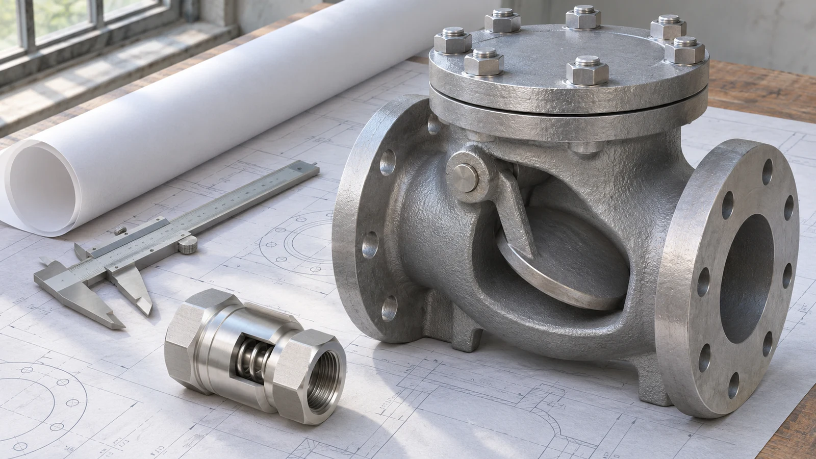
For a replacement, combine the functional reading with photographs, dimensions and the selected drawing. A photo can establish what is physically present, while the P&ID explains its intended place in the system. Neither alone necessarily proves that the current installation agrees with the approved design.
An Original Drawing-Review Exercise
Consider a hypothetical package with three records. The P&ID shows a check permitting flow from pump P-201 into header H-1. The valve schedule calls the item NRV-201 and specifies a spring-assisted assembly. The layout shows a vertical downward pipe segment at that location.
The records establish a functional direction, an identifier and a physical arrangement. They do not yet establish that the selected valve permits vertical downward installation. The useful review question is specific: does the proposed assembly's documentation cover that orientation and the branch operating range?
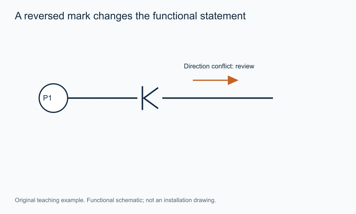
Now suppose a vendor drawing shows an arrow opposite to the P&ID's permitted direction. The discrepancy is not resolved by saying both documents contain a check valve. Record which side connects to the pump and which to the header, then resolve the direction before installation. Equipment names make the issue clear even when the two drawings use different orientations on the page.
Finally, suppose the flow sheet lists a total header capacity of 100 m³/h, but the branch can operate at 20 m³/h when one pump runs at reduced demand. The valve needs the branch cases. A correct symbol cannot supply a missing operating point, and selecting from header flow alone may answer the wrong sizing question.
The exercise yields a short, actionable review record: function identified; direction conflict resolved; installation permission obtained; branch duty assigned. That is a more useful outcome than collecting several visually similar symbols without connecting them to the equipment.
A Reversed Symbol Can Be Found by Tracing the Required Task
Start with a simple functional statement: a pump must discharge from a tank into a higher-pressure header. The check in that branch must permit the discharge route. A mark that permits only the opposite direction conflicts with the stated task, regardless of whether its outline looks familiar.
Use equipment identity rather than page direction to explain the conflict. One drawing may place the pump on the left and another on the right. Describing flow from pump P-201 to header H-1 stays meaningful in both views, while saying the arrow must point right does not.
Now examine whether the line is actually a bypass, return or recirculation path. A check that appears reversed relative to the main process can be correctly oriented for another branch's function. The connections settle that question. Do not reverse a symbol merely because it opposes the nearest large flow arrow on the page.
A disconnected drawing crop can hide that branch context. The useful request is a view containing the adjacent equipment and junctions, not an enlarged icon alone. Once the path is established, the direction can be compared with the valve schedule and selected body marking.
This method does not authorise changing a field installation from a drawing impression. It gives a precise discrepancy to resolve: which connected sides are intended upstream and downstream for the non-return function? The approved resolution should then be reflected across the relevant records.
Read a Pilot Connection as a Circuit Relationship
For a pilot-operated check, identify the two main ports first. Establish the free-flow direction and the direction normally blocked by the check function. Then trace the separate pilot connection to the circuit condition that releases or influences the closure.
A pilot pressure is not interchangeable with the upstream pressure in the main passage. It acts through the selected mechanism and effective areas. The actual product may require a specified relationship among pilot, load and return pressures to achieve release. The symbol establishes that the control connection exists; it does not supply every required force relationship.
Consider a hypothetical hydraulic actuator held by a piloted check. Fluid can enter the held side through the permitted direction. To move the actuator back, the circuit must provide the specified pilot condition and an appropriate discharge route. Replacing the component with a plain check can preserve filling while preventing the intended release path.
A blocked or incorrectly connected pilot line can therefore create a movement problem without a failure of the main check seat. The circuit should be read before assuming the held actuator is mechanically jammed. The selected test and isolation procedure then determines how the hypothesis is evaluated.
This is one reason fluid-power checks should not be specified from a generic process non-return icon. The task includes a controlled release function whose requirements belong to the selected valve and circuit together.
A Bypass Can Defeat the Apparent Non-Return Boundary
A check valve affects the path through its own connections. Another connected route can permit reversal around it. A drawing review should trace those alternatives before concluding that a particular region is protected against reverse circulation.
For example, imagine a check in a pump discharge branch and a separate manual bypass connecting the same two sides. With the bypass open, fluid can use that route without crossing the check. The check can be correctly selected and oriented while the complete arrangement no longer provides the assumed reverse-flow boundary.
The same reasoning applies to interconnected headers and parallel equipment. The shortest line on the page may not be the only physical path. Follow junctions, open connections and the stated valve positions through the whole relevant circuit. A closed isolator shown only as a normal operating note also needs to be interpreted according to the actual operating scenario being reviewed.
The useful conclusion should state its condition: the branch resists header reversal through this path when the bypass is in its defined state. That is more accurate than a broad statement that the pump is protected simply because a check symbol appears nearby.
A schematic can communicate that condition through notes and a clear operating description without becoming a physical layout. The associated procedure and equipment identity then make the functional arrangement usable in practice.
Normal-Flow Direction Does Not Establish Shutoff Performance
A correctly read check symbol gives the intended allowed direction. It does not establish a particular leakage rate in the blocked direction. Bulk reverse-flow prevention and a defined tightness requirement are different levels of performance.
The required reverse differential can matter to the actual seat contact. A selected assembly tested at one pressure can have another behaviour at a much smaller differential. If the process needs to limit seepage between vessels with a small level difference, that duty should be expressed separately from a pump-discharge reversal case.
The fluid also matters. A clean-water seating result does not automatically answer a gas or contaminated-liquid requirement. The applicable test method and acceptance basis should be tied to the selected product and service. The symbol normally cannot communicate that complete basis.
This is a procurement distinction rather than a reason to burden every P&ID with a long test note. The drawing identifies the functional item; the tagged datasheet records the required performance. Keeping the reference consistent gives both documents a clear job.
Compare the P&ID With the Installed Arrangement
A P&ID can show a functional branch horizontally while the actual pipe rises, turns and descends. The selected valve must suit its physical location, not the orientation of the symbol. Compare the functional record with the layout and product instructions before considering the installation complete.
Maintenance access is another information layer. A valve cover may be removable in principle but blocked by a nearby pipe in the actual layout. A check installed inside a package can require removal of another component before inspection. Those conditions can affect the sensible construction choice without changing the P&ID symbol.
A body arrow helps identify the selected product's intended flow direction. Relate it to the connected equipment, especially after a spool has been rotated or a branch has been rerouted. The arrow is useful evidence for orientation, while the product identity and manual establish permitted installation and service conditions.
For an existing line, photographs and dimensions can support that comparison. A photograph alone may hide internal mechanism and rating, while a P&ID alone omits physical clearance. The two sources answer different questions and become stronger when connected by a verified tag and assembly record.
Record an Uncertainty So It Can Be Resolved
A good drawing-review note contains the observed mark, its location, the functional implication and the missing reference. For example: the legend identifies a non-return function, but the selected valve schedule does not state the internal construction or permitted vertical-downward duty. That note gives the next reviewer a specific question to answer.
Another useful note identifies a conflict: the P&ID permits pump-to-header flow, while a vendor view appears to show the opposite connected direction. Include the equipment names and drawing revisions so the issue remains clear if the page orientation changes.
Avoid replacing uncertainty with a guessed standard number or an assumed valve type. An unsupported precise answer is less useful than a bounded functional conclusion with a clearly identified missing document. The goal is to complete the engineering record, not to appear certain from an isolated icon.
Once the selected information is obtained, update the applicable record and retain the basis. A later replacement should not have to rediscover the same direction and installation questions from scratch. That traceability is a practical outcome of reading the symbol carefully.
Four Small Symbol Changes That Alter the Reading
Adding a spring changes the depicted closing mechanism, while leaving the basic permitted direction recognisable under the defined convention. The extra mark does not assign a numerical spring force. Its practical consequence is a different opening and closing balance that must be specified for the actual product.
Adding a pilot connection introduces another way to influence the blocked path. That can change the circuit from a plain non-return function into a controlled release function. The connection should be traced to its source rather than treated as a stray instrument line.
Adding a straining function at a suction intake introduces a debris-interception task and another resistance. The resulting foot-valve assembly has to be considered with the suction system. The combined symbol does not provide a strainer opening or a fouling allowance.
Adding a manually operated stop function introduces a deliberate operating condition in addition to automatic non-return behaviour. The selected construction determines exactly what can be prevented or released. A combined label should lead to that functional explanation rather than an assumed universal operating sequence.
These changes illustrate a useful reading principle: an extra mark should add a defined function. If its purpose cannot be explained in a sentence, return to the legend and references before assigning it a meaning. Decoration is not the purpose of an engineering symbol.
A Numerical Note Beside the Symbol Has Its Own Basis
A check-valve note may specify an opening differential, a pressure rating, a size or a tag number. Those numbers describe different things. A value followed by bar is not automatically the line pressure, and a number embedded in a tag is not automatically a nominal diameter.
For a hypothetical note stating a cracking differential of 0.2 bar, the intended meaning concerns the onset of opening under the stated test basis. It does not state the valve's pressure drop when it passes ten cubic metres per hour. A spring or moving element can continue travelling as flow increases.
An orientation change can also alter the force balance for some products. The note's test arrangement should therefore remain connected to the selected specification where it matters. A symbol rotated on a schematic does not establish that the same numerical opening condition applies in the field.
A pressure-class note addresses another subject. It identifies a rating basis whose material and temperature conditions need the applicable documentation. It should not be used as a substitute for cracking pressure, seat leakage or dynamic response. Keeping those quantities in separate schedule fields prevents a visually neat but technically ambiguous record.
A size note identifies the mechanical connection basis rather than the whole operating envelope. Two valves with the same nominal size can have different opening characteristics and internal passages. The symbol and note together can identify the item while still leaving legitimate selection work for the datasheet.
A Flow Balance Completes the Functional Reading
The P&ID tells the reader which branches connect. A flow balance assigns quantities to the relevant operating cases. With parallel equipment, a header total cannot automatically be copied into every branch's valve duty.
Suppose two hypothetical pumps each deliver thirty cubic metres per hour into a common line when both run. The total header flow is sixty, while each branch check sees thirty under that case. If one pump operates at a reduced rate of twelve, that branch's check sees twelve, not the original sixty.
The arithmetic is simple, but the document relationship matters. A valve list populated from the wrong flow location can be internally consistent in units while describing the wrong physical duty. Trace the tagged valve to its position before assigning the numerical cases.
A recirculation branch can change the balance again. A pump's total discharge can split between a process path and a return path, so the check on one path need not see the whole pump output. The schematic establishes the topology; the operating balance establishes the quantities.
This is a concrete benefit of reading beyond the icon. The result is not merely recognition of a non-return component, but a correct association among its function, connected equipment and actual branch flow. That association supports a meaningful selection enquiry.
Drawing Revision and Equipment Identity Must Stay Connected
A drawing revision can change a branch connection without changing the familiar check symbol. The functional consequence can still be substantial. A return line moved to another header may expose the check to another reverse pressure or operating sequence.
The tag and revision should therefore travel with any extracted image used for enquiry or review. A screenshot without its identity can remain visually clear while becoming impossible to relate to the current design. The drawing reader should know which version the interpretation describes.
A vendor drawing may also use another view or internal convention. Translate both into connected equipment names and permitted paths before deciding they conflict. Sometimes the difference is only page orientation; sometimes it reveals a real reversal. The functional statement separates those cases.
Once a discrepancy is resolved, retain the updated schedule or reference with the drawing. A later spare-parts purchase should not have to rely on an informal message explaining why an arrow was changed. The documented function and selected product should remain traceable together.
This is ordinary engineering communication rather than additional bureaucracy. It preserves the meaning established during review, so the next person can identify the same duty without repeating the investigation from an isolated symbol.
A Gravity-Flow Example Shows What a Pressure Note Can Change
Suppose two open water tanks have a level difference of thirty centimetres and are connected by a full line. With an assumed density of one thousand kilograms per cubic metre and gravitational acceleration of 9.81 metres per second squared, the available hydrostatic difference is approximately 2,943 pascals, or 0.0294 bar, before flow losses.
Now suppose the proposed check's documented cracking differential is 0.2 bar under the applicable example conditions. The level difference alone is below that opening requirement. A correctly oriented check symbol would therefore not establish that the intended gravity transfer can begin through this hypothetical assembly.
These are transparent assumed conditions, not a test of a product. The example separates direction from available driving differential. The symbol answers which way the valve permits flow when its operating conditions are met; the pressure budget answers whether the system can produce those conditions.
A spring note can consequently be important even in a low-pressure system. Choosing a strong closing spring without considering the available head can defeat the intended forward task. Conversely, a low cracking value still does not establish the pressure loss at the required flow. Initial opening and sustained capacity remain separate questions.
The connected tank pressures must also be understood. If either tank is pressurised rather than open, the gas-space pressures contribute to the driving difference. Elevation alone no longer describes the whole budget. State the actual boundaries so a supplier does not size from a level sketch that omits a pressure source.
This example gives the drawing reader a useful next step: pair the functional direction with the operating differential and required flow. It is a more complete interpretation than treating the arrow and nominal connection size as sufficient evidence that the transfer will work.
A Return Line May Intentionally Oppose the Main Flow
A recirculation or return branch can have a check oriented opposite to the direction in the adjacent main line. That is not automatically a drafting error. The branch may be intended to return fluid from downstream equipment toward a source or another defined location.
Trace its endpoints and the operating condition in which it should pass flow. Then express the direction using equipment names. This prevents a reviewer from reversing a legitimate return check simply to make every arrow on a page point the same way.
The branch's numerical duty also needs its own basis. It may carry only part of a pump's output or flow during a particular operating mode. The main-line total is not automatically the return-check flow. Functional topology and the operating balance should be read together.
A strainer note should also distinguish an opening dimension from a filtration-performance claim. A perforation size describes part of the physical passage, while retention of a particular material can depend on its shape and the complete element. The foot-valve function and the required debris duty should remain linked in the specification, rather than inferred from a mesh pattern drawn beside a check symbol. Where a pressure note applies in only one direction, preserve that condition in the valve schedule and selected component record.
From a Symbol to a Complete Product Enquiry
A symbol becomes commercially useful when its function is translated into a duty. State the permitted direction in terms of connected equipment, identify the tagged location and provide the medium, temperature, pressures and flow range. Include solids or contamination where relevant.
Add the physical conditions that a P&ID leaves out: connection standard, available length, installation orientation and access. If the system has a demanding shutdown, state the operating scenario and available dynamic information rather than request a generic non-slam product with no context.
The engineering guides area can support that preparation. A product proposal should identify what construction is offered and how it addresses the stated duty. The functional symbol remains useful as a reference, but it should not be the sole attachment to the enquiry.
Use the VantaValve quotation form with the tagged duty and the relevant drawing extract. A clear description of the required reverse-flow protection will reduce ambiguity more than specifying a valve from the appearance of a symbol alone.
FAQs on Check Valve Symbols
These questions cover common ambiguities encountered when reading mixed drawing packages.
Is a check-valve symbol always an arrow?
No. The representation depends on the drawing convention. Some process diagrams use a directional closure mark, while fluid-power diagrams can show a poppet or ball, seat and additional functional detail. A plain process-flow arrow is not automatically a check valve.
Does a spring mark specify cracking pressure?
It indicates spring assistance under the relevant convention, but it does not supply a numerical opening differential. The value and its test conditions belong in the selected component specification or a clear drawing note.
Can the symbol identify a swing check?
A project may use a more specific mark or note, but a generic non-return symbol does not reliably identify the internal mechanism. Use the schedule and datasheet to establish the selected construction.
Is the check-valve tag CV universal?
No. Abbreviations and tag formats vary by project and context. Read the project's naming rules, particularly where CV might refer to a control valve and Cv refers to a flow coefficient.
Conclusion
Read a check valve symbol as a functional statement about permitted flow and resistance to reversal. Establish the drawing convention, trace the connected equipment and use the legend to identify any spring or pilot function.
Then move from function to specification through the tagged schedule, operating duty and selected product data. The symbol tells you why the check is there; the complete document set establishes which assembly can perform that job in the actual installation.
Need a valve for your application?
Send your valve type, operating conditions and quantity. Our team can help review the options for your inquiry.
Request a Quote →