Ball Valve Symbol: Read the Body, Actuator and Port Paths
Ball Valve Symbol: Read the Body, Actuator and Port Paths
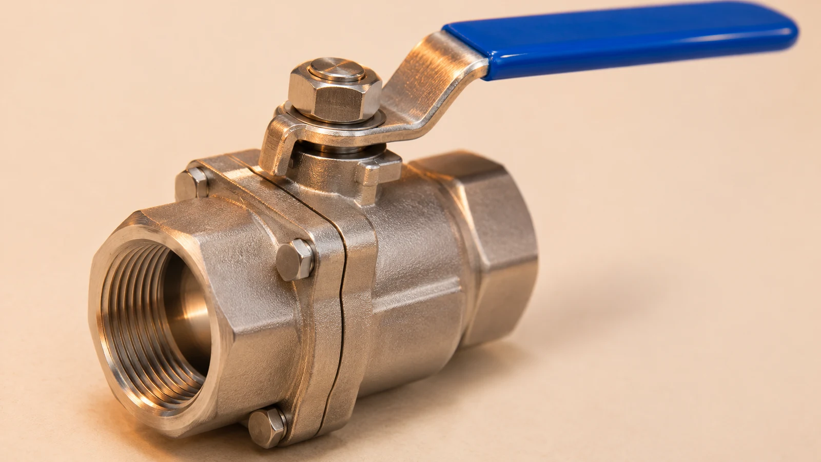
A ball valve symbol represents a valve that controls a passage by rotating a bored ball. On many process diagrams, a ball-specific detail is added to a general valve body mark; other drawing libraries use a different agreed representation. Read the project's legend first, then the actuator, tag and connected ports. The symbol identifies the function and arrangement without showing every internal part.
Three distinctions change the reading: two-way isolation versus multiport routing, manual versus actuated movement, and normal position versus a defined failure action. Body material, bore size, pressure class and seat construction normally require supporting documents.
This guide uses original teaching diagrams with explicitly defined conventions. They are intended to make the reading method clear, rather than reproduce a proprietary standards symbol sheet or replace a project's approved legend.
Recognise the Valve Body Before Reading the Operator
A common teaching representation begins with two opposed triangles meeting at the centre of the pipe and adds a circle at their intersection to identify a ball construction. The exact fill, scale and detail can vary across libraries. A circle by itself is not enough to identify a ball valve in every drawing context.
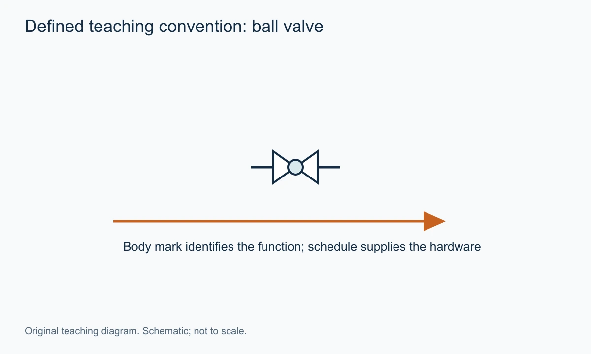
The practical method is to compare the mark with the legend entry, not with a remembered screenshot. A similar-looking central detail may be used differently in another library. Read the valve tag and schedule alongside the shape when the distinction matters to a purchase or modification.
The pipe line through the symbol represents a connected path. It is not normally a scale drawing of the drilled bore. The VantaValve ball valve category is the corresponding product-family route, while the selected datasheet establishes what hardware satisfies the depicted function.
An exterior handle is also not a complete identification method. Other quarter-turn families can have levers, and an automated valve may have no manual handle visible. The internal bored ball is the defining mechanism, while the operator determines how it is moved.
What Standards References Do and Do Not Establish
Process diagram symbols and instrumentation identifiers have related but distinct roles. ISO10628-2 addresses symbols for chemical and petrochemical diagrams. ISA's instrumentation and control work addresses the identification and depiction of measurement and control functions. A project's drawing package can reference these alongside its own approved legend and specifications.
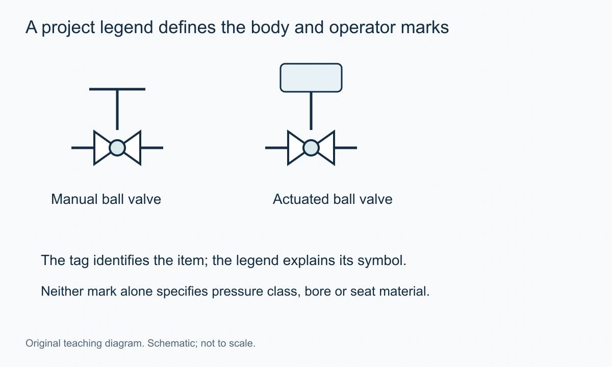
A standards reference does not mean every online valve icon is an exact, current reproduction of that standard. It also does not supply a valve's materials or pressure rating. Keep the visual convention, instrument identification and product specification separate when reviewing the drawing.
For a hydraulic or pneumatic circuit, the applicable symbol system can be different again. ISO1219-1 addresses fluid-power symbols. A process ball valve on a P&ID and a fluid-power component in a hydraulic circuit should not be interpreted using an unexamined mix of libraries.
The useful working rule is simple: the approved drawing legend establishes the local meaning, while the associated engineering documents establish the hardware and duty. Where two documents conflict, record the conflict rather than invent a hybrid interpretation.
Two-Way Ball Valves: One Controlled Connection
A two-way ball valve has two principal process ports. In a conventional isolating arrangement, rotating the ball aligns its bore with the line to open the passage or turns the solid portion across the line to close it. The P&ID body mark identifies that valve location; it may not depict the actual operating state unless the convention explicitly does so.
A normal-position note is more reliable than inferring state from an icon that the library draws the same way for every valve. If the drawing uses separate open and closed representations, the legend should say so. A symbol's graphic appearance and a written state note should agree, but one should not be guessed from the other.
The common handle rule for a simple two-way lever valve is that an aligned lever often indicates an open passage and a transverse lever a closed passage. That is an equipment observation, not a universal P&ID rule. Couplings, special handles and multiport arrangements can require another interpretation. Follow the actual manufacturer's indicator and documentation.
The full-port ball valve article explains another distinction the symbol often leaves out: a full-port and a reduced-port valve may share the same basic drawing mark. The nominal connection size does not establish the internal bore.
Manual, Pneumatic, Electric and Hydraulic Operators
An operator mark attached to the valve body adds information about how the ball is moved. It should be read as an addition to the ball-valve function, rather than as a different valve family. The same basic body function can be operated by a lever, gearbox or an actuator.
A manual operator means a person supplies the input through the specified mechanism. The drawing may distinguish a lever from a handwheel or show only a general manual mark. The available access and required torque still belong to the mechanical review, not the symbol alone.
A pneumatic actuator uses air to move the valve. A spring-return arrangement can provide a defined movement when the air is lost, while a double-acting arrangement uses pressure on opposing sides to move in both directions. The word pneumatic does not establish which construction is present or what the complete assembly does on each failure event.
An electric actuator uses a motor and associated controls. A generic electric mark does not guarantee a stored-energy failure action. An actuator can stop or remain in position when power is lost unless a particular assembly provides another response. The required event and resulting position should be stated explicitly.
A hydraulic actuator uses pressurised liquid and can have its own power, accumulator and control arrangements. Those details can affect movement and failure response. A small actuator symbol on the P&ID cannot replace the actuator schematic and functional description where the distinction matters.
For a remote isolator, the information should therefore answer three separate questions: what moves the valve, what commands it, and what happens when the specified source or command is lost. One operator icon may answer only the first.
Normal Position, Commanded Position and Failure Action
Normal open describes an intended operating condition. Fail open describes a response to a defined loss or event. Open feedback describes a reported condition. These statements can all refer to the same valve, but they are not interchangeable.
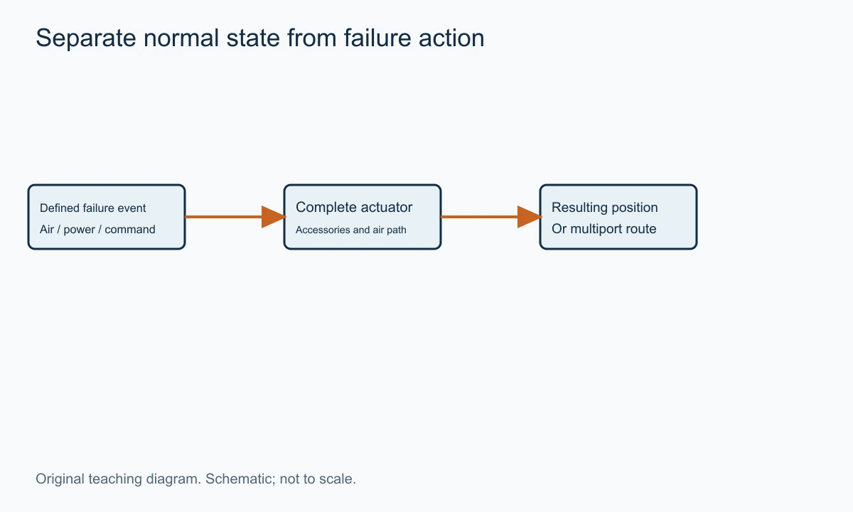
A valve can be normally open and fail closed. For example, the process may require it open during production but closed when its specified shutdown action occurs. Another valve can be normally closed and fail open for a different process reason. The appropriate choice comes from the process requirement, not a general preference for one direction.
The failure event must also be identified. Loss of electrical command, loss of air, loss of electrical power to a solenoid and loss of actuator power are different events. A complete assembly may respond differently to them. A spring-return actuator can support a defined action, but trapped air or the accessory arrangement can influence how and when that movement occurs.
A project may use abbreviations such as FO or FC for a defined failure action. Treat them according to its legend and functional description. Do not infer that a generic symbol or an unlabelled arrow supplies the same information in every project.
A failure-action note is also not a complete safety-system specification. Required response time, testing, diagnostic coverage and the rest of the system belong to a defined project assessment where applicable. The P&ID should be consistent with that assessment, rather than be treated as evidence that it has already been completed.
Three-Way Ball Valves: Read the Port Map, Not the Handle Alone
A three-way valve has three principal process connections and an internal route that changes with ball position. L-port and T-port describe familiar bore patterns. They do not by themselves establish every operating position, seat arrangement or permitted pressure direction.
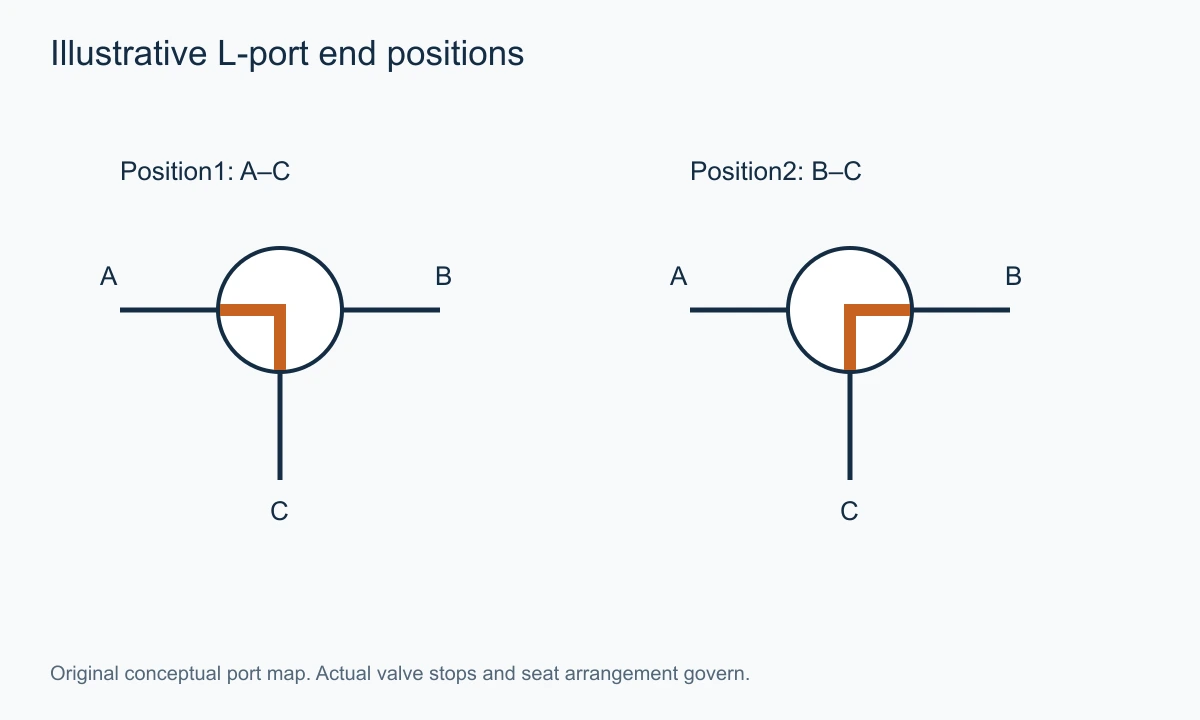
Label the physical ports before interpreting the route. In the original examples here, A is left, B is right and C is bottom. Those labels are teaching choices, not mandatory manufacturer port numbers. The actual body and actuator documentation should provide the applicable mapping.
For an illustrative L-port arrangement, one position can connect A to C while blocking B; a quarter-turn position can connect B to C while blocking A. That makes C a common connection for the two selected routes in this example. Another construction or indexing arrangement can use different stops, so the table must follow the selected product.
| Illustrative L-port position | Connected ports | Port isolated from that route |
|---|---|---|
| Position1 | A–C | B |
| Position2 | B–C | A |
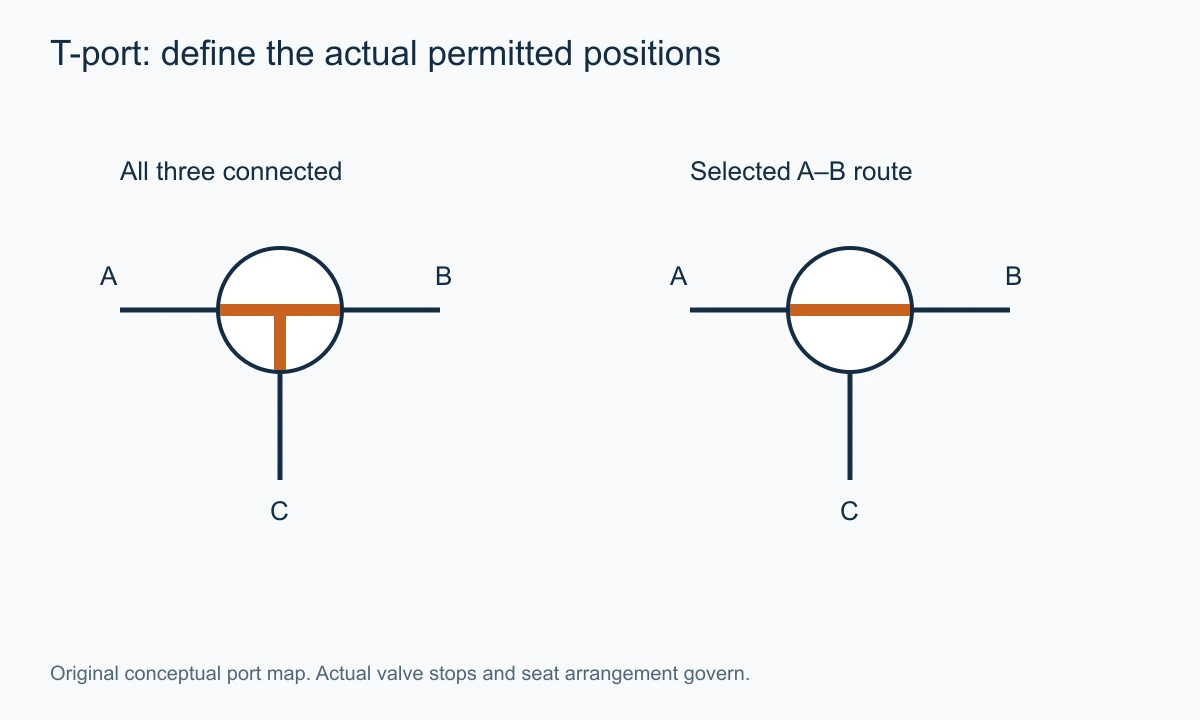
A T-port can provide other combinations, potentially including communication among all three ports in a particular position. Whether a selected valve has a complete shutoff position depends on its bore, stops and seat construction. A T-shaped line in a symbol is therefore not a promise that every desired combination is available.
| Illustrative T-port position | Intended connection shown in this teaching example |
|---|---|
| Position1 | A–B–C communicate |
| Position2 | A–B communicate; C excluded from the depicted route |
| Position3 | A–C communicate; B excluded from the depicted route |
| Position4 | B–C communicate; A excluded from the depicted route |
The second table is a conceptual route inventory, not a claim that a particular 90-degree actuator can reach all four positions. The selected stops and indexing determine which positions are used. A real enquiry should identify the required routes, transition behaviour and pressure conditions rather than request a T-port valve without a position table.
Emerson's KTM three-way ball-valve manual distinguishes two-seat and four-seat constructions and their flow arrangements. It is a manufacturer example of why port shape and seat arrangement must be considered together. Its restrictions belong to the named models.
Flow During Travel Can Matter as Much as the End Positions
Two correct end-position sketches do not describe everything that happens while the ball rotates. A route can open before another closes, remain partly connected or pass through a restricted intermediate condition, depending on the design. The transition can matter when the fluids must not mix or when interruption is unacceptable.
A diverting application may tolerate a brief overlap between routes, while another requires a defined isolation sequence. Those are process requirements that should be stated before selecting a multiport assembly. The symbol alone seldom establishes the transition behaviour.
The same issue applies to trapped fluid. A multiport construction can contain cavities or isolated volumes whose pressure behaviour needs consideration. A route table should identify which process ports communicate at each selected position, while the manufacturer's construction information addresses internal cavities and relief arrangements.
A valve described as mixing-capable does not automatically provide a controlled mixing ratio. It may connect streams without a regulating characteristic suitable for the intended control task. If the process needs continuous proportioning, request sizing and control information for that duty rather than rely on the existence of three ports.
The three-way ball valve product route is the relevant destination for discussing a specific route requirement. Provide a port map and position table so both parties refer to the same physical connections.
End-Connection Marks and the Information They Leave Out
Some drawing libraries add marks for flanged, threaded or welded connections. They can be useful during interpretation, but their appearance varies. Read the legend instead of assigning a connection from a small circle, square or line borrowed from another drawing system.
Even a correctly read flanged symbol does not provide the flange standard, pressure class, facing or material. A threaded mark does not specify NPT versus BSP or another thread. A weld mark does not establish end preparation, wall compatibility or the applicable welding procedure.
The line class and selected valve datasheet provide that detail. The P&ID tells the reader which functional components are connected; the mechanical documents determine how the pressure boundary is made. A purchase enquiry needs both levels where the interface is constrained.
This is especially important for replacement. A valve that looks identical on the P&ID can have a different face-to-face length or bore. The ball-valve parts article helps distinguish the body, seats, ball and stem arrangement, while the selected drawing supplies the dimensions.
Ball Valve Symbol Versus Check, Globe and Gate Symbols
The ball-valve mark identifies a deliberately operated rotary closure in the relevant library. A check-valve mark identifies automatic resistance to reversal. A globe or gate mark identifies a different closure mechanism. Confusing them changes the system's intended function, not only its appearance.
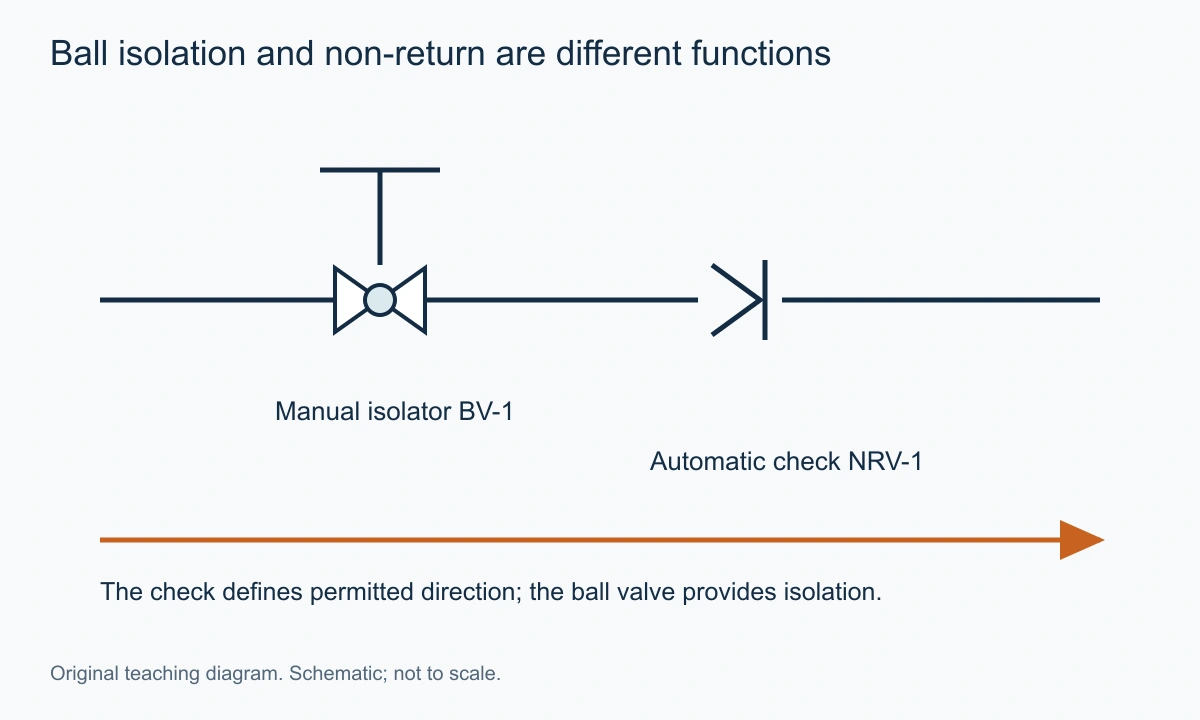
A plain check cannot be commanded to isolate a line in the same way as a suitable actuated ball valve. A ball valve left open does not automatically prevent reverse flow. The two can sit beside each other because they perform complementary jobs.
A globe valve can be selected for regulation, while an ordinary full-port ball isolator is intended for another duty. A V-port or segmented ball control construction is a further distinction. A general ball symbol may not communicate that specialised trim without another note or schedule reference.
A gate symbol identifies a closure that withdraws across the passage. The existing gate-valve symbol guide provides that related reading task. The most reliable comparison uses the project's legend entries side by side, then confirms the tagged specification.
For product-family selection, the types of ball valves article develops support, body and flow-path distinctions. Those construction choices should not be guessed from a generic P&ID icon.
An Original Reading Exercise: A Tank-Transfer Selector
Consider a hypothetical transfer system with a pump feeding port C of a three-way selector. Port A leads to tank A and port B to tank B. The process requires delivery to one tank at a time, with no intentional route between the tank branches through the selected valve position.
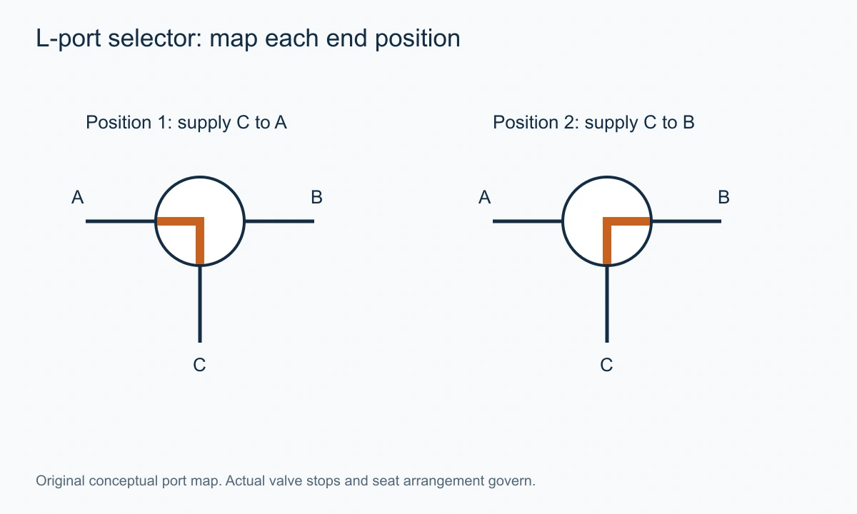
The first drawing task is to label the ports and define the two operating connections: C–A and C–B. The next is to state what the valve must do during travel. If the process cannot tolerate temporary communication or interrupted flow, that requirement must be addressed in the selected assembly and operating sequence.
Now add an actuator. The drawing needs to identify the required command and any defined failure route. “Fail open” is ambiguous for this three-port task: open to which tank, and with which other port blocked? A failure position should be expressed as a port connection, not only a two-way open/closed phrase.
Next consider feedback. An indication labelled “tank A selected” should correspond to the intended physical position and route. A motor running signal or solenoid energised signal is not the same as confirmed valve position. The cause-and-effect and feedback documents should use compatible terms.
Finally consider a replacement. A new three-way valve with the same port sizes may have different indexing or seat arrangement. The port table, pressure directions and actuator travel must be matched. A familiar T-shaped symbol cannot establish equivalence on its own.
The exercise produces a clear enquiry: actual port identities, required end-position routes, transition constraints, pressures and defined failure route. That is enough to begin a meaningful product discussion without pretending the P&ID contains every construction detail.
Read an Actuated Two-Way Valve as Three Connected Statements
Take a hypothetical valve tagged BV-310 on a product-transfer line. The approved legend identifies its body mark as a ball valve, the operator mark as pneumatic, and the note FC as closed on the defined loss of actuator air. The ordinary production note says the valve is normally open. These statements are compatible: the normal process route is open, while the specified air-loss response is closed.
Now trace the command. A controller or shutdown system may energise a solenoid that affects the actuator air path. That electrical relationship should agree with the pneumatic schematic. An energised coil is an electrical state; it is not a direct measurement that the ball has reached its intended position.
Position indication adds a third statement. An open or closed switch reports the condition its mechanism detects. The selected linkage and setting determine how that corresponds to the valve movement. A switch can be useful for sequencing without proving the specified internal leakage performance.
A clear review therefore produces three sentences: what the process passage does, what event commands or releases the movement, and what observation confirms the required position. Those sentences can then be compared with the cause-and-effect and actuator documents. This is more reliable than reading the small actuator mark as if it contained the complete control philosophy.
If the failure note is missing, do not infer it from a familiar air actuator shape. The drawing can correctly identify pneumatic operation while leaving the spring and accessory arrangement unresolved. The useful question is the specified event and final state, not whether pneumatic valves generally fail one way.
A Multiport Position Table Needs Physical Port Identity
A port table should begin with a view that identifies the actual connections. A left port in a plan view can become the right port when viewed from the opposite side. Manufacturer letters and numbers should be preserved, with the connected equipment written beside them. This removes a common source of apparently contradictory route descriptions.
Assume the selected drawing identifies port C as the pump connection, port A as tank A and port B as tank B. The intended first end position connects C to A and isolates B from that route. The second connects C to B and isolates A. Those statements should be written in the same order in the P&ID note, actuator schedule and commissioning record.
The actuator's rotation direction is another coordinate system. Clockwise depends on the viewing direction, so the applicable view needs to be stated. A clockwise command observed from the actuator top cannot be translated safely from a sketch viewed through the opposite end without accounting for that change.
A replacement can preserve the same physical pipe connections while changing the internal indexing. That is why matching an L-shaped mark is not enough. The actual end positions, travel stops, seat arrangement and indicated routes need to agree with the installed process task.
The route through the transition also belongs in the enquiry when it matters. A process that cannot tolerate cross-communication needs more than correct final positions. A process that must never deadhead a pump needs the travel sequence assessed as part of its operating arrangement. The selected valve and control sequence must address the required behaviour together.
A Three-Position Request Is Not Automatically a Quarter-Turn Task
A basic two-position actuator is selected to move between its specified stops. A drawing that shows three useful flow routes does not establish that the actuator can stop at all three. The body and actuator may need another indexing or positioning arrangement to provide that task.
For an illustrative T-port application, a process might request an A–B route, an A–C route and a position connecting all three ports. The route inventory is only the first step. The selected assembly must identify the angular positions, permitted transition paths and whether the actuator can hold the required intermediate state under the process load.
A general open and closed indication is insufficient for that three-route task. Feedback should identify the actual selected route or a position from which the route can be established according to the documented mapping. Calling every non-closed state open can conceal which equipment is connected.
The same clarity is needed for failure action. A three-way valve may be required to return to the A–C route on a defined event. Writing fail open leaves unanswered whether B is also connected and whether the transition meets the process requirement. The failure statement should name the ports or connected equipment.
These distinctions turn a symbol question into a workable specification without choosing the construction prematurely. The supplier can assess the body, stops and operator against the requested route table, rather than quote a three-way valve that happens to have the right connection sizes.
Drawing Changes Should Follow the Function Across Documents
Suppose a project changes a manual two-way valve to remote pneumatic operation. Adding an actuator mark to the P&ID is one part of the change. The assembly also needs a command, air supply, defined failure response where required, access and any position indication used by the operating sequence.
The valve schedule must identify the changed assembly, while the actuator and pneumatic documents describe how it moves. If the process uses feedback to permit another pump or valve action, the relevant logic and commissioning records need to agree. A correct icon can coexist with an incomplete functional change.
Now suppose the change is from two separate isolators to one multiport selector. The end-position routes and travel behaviour must be assessed, not simply drawn as a compact replacement. The new arrangement may create another communication path or eliminate an independently operated boundary that the old process used.
A useful revision note explains the resulting function, the affected tagged items and the associated documents. It need not narrate every drafting edit. The person reviewing it should be able to establish what the process can now connect and how the assembly is commanded and indicated.
For an existing installation, retain the approved revision and the actual equipment identity together. An old P&ID can explain the original intention without accurately describing a later field modification. The review should resolve that difference through the project's process rather than silently choosing whichever representation is convenient.
Use the Symbol to Ask a Better Product Question
A product enquiry becomes clearer when it translates each drawing layer into a requirement. The body mark becomes a valve function. The connected lines become named ports and a medium. The operator becomes an available energy source and command. The action note becomes a response to a defined event. The tag connects the result to the project record.
What remains absent should be supplied as duty data. Pressure and temperature belong to the operating envelope; connection and length belong to the mechanical interface; leakage and external containment belong to acceptance requirements. The symbol does not need to carry all of them graphically for the enquiry to be complete.
This is especially useful when the initial request is only a screenshot. Add enough surrounding context to identify the equipment and routes, then list the missing numerical conditions. A supplier can then distinguish identification work from actual selection. A confident guess at a material or rating from the icon would provide less useful information.
The result is a practical reading habit: recognise, trace, describe and then specify. The graphic gives orientation; the connected system gives meaning; the duty and selected product data establish what can actually be supplied.
An Open T-Port Does Not Guarantee an Equal Split
A T-shaped passage can connect three ports, but it does not prescribe the flow leaving each branch. The connected pressures and resistances determine that distribution. Two arrows leaving the same valve should not be read as a fifty-fifty divider unless a separate regulating function establishes that result.
Take an illustrative water arrangement with a common inlet at three bar and two users held at 2.5 bar. Assume the first complete branch has an equivalent Kv of twenty and the second an equivalent Kv of ten. Under the simple non-choked liquid relationship and an assumed specific gravity of one, their flows are approximately 14.14 and 7.07 cubic metres per hour respectively.
The total is about 21.21 cubic metres per hour, with a two-to-one split. The numbers are assumed to demonstrate the network consequence; they are not capacities of a three-way product. A real valve contributes its own losses and route-dependent coefficients, so the complete branches must be evaluated.
Now change one user's pressure while leaving the valve in the same position. The flow split changes even though the port diagram is unchanged. If pressure conditions reverse, another direction of flow may become possible through a connected passage. A ball valve does not add a non-return function merely because the drafter placed arrows beside the normal flow routes.
This is useful when interpreting mixing or dividing language. A valve can make communication available without controlling the ratio or guaranteeing direction under every pressure condition. A process requiring a controlled split needs the appropriate regulating arrangement and measurements.
A good route table therefore states connectivity, while a flow balance states quantities. Keeping them separate makes both clearer. The table should not acquire invented equal percentages that the mechanism does not enforce, and a flow calculation should not assume a route that the selected position cannot provide.
A Switching-Time Calculation Shows Why Transition Matters
Consider another teaching example in which a pump supplies two hundred litres per minute through a selector. If the valve takes two seconds to move between end positions, the pump supplies approximately 6.67 litres during that time, assuming its flow remains constant. That volume must go somewhere in the actual changing passage.
The calculation does not predict which route receives the volume. It could be divided, interrupted or redirected according to the valve and system response. It simply demonstrates that travel is a physical operating interval, not an instantaneous change between two tidy drawings.
For a process that must keep two products separate, even a short overlap may matter. The required assessment concerns the actual internal route during movement and the operating sequence. A final-position table alone cannot establish the amount of crossover.
For a process that cannot tolerate interruption, a closed transition can pose another problem. The pump and upstream volume respond to the restriction, and the actual flow may fall rather than remain at the assumed constant value. The six-point-six-seven-litre result is therefore an input-volume scale under its stated assumption, not a prediction of stored or displaced volume in every system.
State the transition requirement in functional language: temporary communication permitted or prohibited, interruption permitted or limited, and any required control sequence. The supplier can then assess whether the proposed valve and actuator provide that behaviour. A more attractive symbol cannot change the underlying route.
This example also explains why a replacement actuator speed can matter even when the valve body stays the same. Faster or slower travel changes the time spent in transitional connections. It should be evaluated against the process requirement rather than altered solely to improve a stroke-time figure.
Distinguish a Valve Position From a Permissive
A control system may require a valve's reported position before allowing another action. That reported condition is a permissive in the defined sequence. The P&ID can show relevant instruments, but the logic documents establish how those observations are used.
For a tank selector, an indication that port C is connected to tank A can be used in a documented sequence. A generic actuator running signal is different: it can indicate movement without establishing which end position has been reached. A commanded position is different again from a reported position.
The device providing feedback must be identified. A limit switch, an actuator encoder and a positioner travel signal have different measurement paths. Their interpretation should follow the selected assembly and configuration rather than a general assumption that all feedback directly measures internal port communication.
A discrepancy between command and indication is an observation to resolve through the approved system procedure. It is not a reason to infer the valve state from the command alone. The actual process may need a defined response to that discrepancy, but the appropriate response belongs to its operating and protection design.
The drawing reader can still make a useful contribution without designing that logic. Identify which state is required, which instrument reports it and which document defines the sequence. That makes the missing information concrete and keeps the small valve icon from being burdened with a function it does not express.
A Handwheel, Lever and Gear Indicator Have Different Relationships to the Ball
A direct lever often provides a simple visual relationship to a two-way ball's bore, but an indicator on a gearbox can use another marking. The gear input can rotate many turns while the output moves through its selected quarter turn. The handwheel's instantaneous orientation is therefore not the ball position.
A manual override on an actuator adds another relationship. Its engaged or disengaged condition can affect how the assembly follows automatic commands. The existence of a handwheel symbol does not establish that a person may operate it under every process condition or that it is always mechanically connected in the same way.
For multiport equipment, an external indicator should identify the internal route or a position that maps unambiguously to it. A handle aligned with one pipe may not identify every connected port in a T-port construction. Use the selected stem marking or route diagram rather than extending the simple two-way lever rule.
This is an identification issue as well as an operating one. A replacement indicator mounted in another orientation can display a familiar arrow while representing another internal connection. The assembly record and commissioning procedure should preserve the intended relationship.
The useful diagram therefore connects three things: physical port identities, selected angular positions and external indication. When all three agree, the reader can translate a reported position into the intended route. When one is missing, the uncertainty should be stated instead of hidden behind an open or closed label.
Build a Route Matrix for a More Complex Package
A route matrix lists each required operating state against the connections it permits. For a package with a source, two destinations and a cleaning connection, the matrix can expose whether one three-way valve actually provides all required functions or whether the proposal omits a route.
Start with equipment names rather than port letters. State source-to-destination-A, source-to-destination-B and any cleaning or draining task. Then map those tasks to the selected valve positions. This avoids changing the process requirement merely to suit the first convenient port diagram.
Next identify combinations that must never communicate in the intended arrangement. The matrix can record that requirement without pretending the symbol alone enforces it. The selected valves, control sequence and isolation design must provide the actual boundaries.
The matrix can also show simultaneous tasks. A system that must deliver to one destination while another branch is cleaned may need independent functions that one selector does not provide. A compact multiport valve is valuable only when its actual routes match the process, not because it reduces the number of bodies on the drawing.
Finally relate each state to the command and indication. The result is a small functional specification that a supplier and control engineer can both interpret. It is a useful original document even before a final product is chosen, because it makes the required connections explicit.
Count the Physical Item, Not Every Graphic Attached to It
A valve symbol can have an actuator, position indication and other instrument marks attached to the same tagged assembly. Those marks do not necessarily represent additional process valves. A quantity takeoff should identify the physical assembly and then its accessories as a defined scope.
For an illustrative remotely operated isolator, the ball body is one process valve. A position switch can be a separate supplied instrument, while a solenoid controls an actuator-air path. The package may contain several components without containing several identical ball valves. Read the tag relationships and schedule before turning every nearby mark into another valve quantity.
The reverse error is also possible. Two independent valves can be drawn close together within a package boundary. A rectangular enclosure around them does not merge their functions into one body. The selected package drawing and bill of materials establish the actual construction.
This matters commercially because a valve-only price and a complete actuated-assembly price have different scope. A P&ID can identify the required functions while the quotation needs to state which operator, feedback and switching components are included. Counting icons alone cannot establish that scope.
Follow Off-Page References Before Assigning a Route
A line can leave one P&ID and continue on another. The off-page reference connects the two functional views. A local ball valve may appear to lead to a generic outlet until the continuation identifies a specific header, tank or user.
Match the line identity and reference rather than only the direction of the arrow on the page edge. The next drawing can use another layout orientation. Connected equipment names and line numbers preserve the route even when the paper arrangement changes.
A multiport selector close to a page break deserves particular care. Its three connections can continue to different drawings, and a small crop can hide one of them. Complete the port map before deciding which connection is common or whether two sources can communicate in a selected position.
A revision can change the continuation while leaving the local valve icon unchanged. Retain the drawing versions used for the route review. The interpretation should describe the current connected system, not an accidental mixture of an old upstream sheet and a new downstream sheet.
Process Flow Diagrams and P&IDs Have Different Detail
A process flow diagram can show the main material route without identifying every isolation valve and instrument. A P&ID adds another level of functional detail. The absence of an actuator from a simplified process diagram does not necessarily conflict with an actuated valve on the detailed drawing.
Use each document for its stated purpose. The process flow and balance establish the broader operation, while the P&ID and related schedules identify the functional items. The mechanical drawing and selected product data then establish physical arrangement and construction.
For a product enquiry, include the level of detail needed to explain the actual valve task. A full plant drawing can contain far more information than the supplier needs, while an isolated body icon can omit the route and operator function. A relevant extract with connected equipment, tag, legend reference and duty is often clearer.
The same principle applies to digital symbol libraries. A library provides consistent graphics, but the person using it still has to assign the correct function and references. Selecting an icon named ball valve cannot decide port routing, failure response or materials for the project.
A Clean Graphic Helps Preserve the Function
A symbol must remain readable at the scale at which the drawing is used. Fine central detail can disappear in a low-resolution screenshot, making a ball-specific mark look like another general valve. Enlarging a blurred crop cannot recover information that was lost during export.
Retain a vector or sufficiently clear original for the engineering record and use the approved legend alongside it. The teaching images here use their own defined convention so the function can be explained in plain language. They should not be silently substituted into a controlled project library without the project's review process.
Clarity is functional, not decorative. A readable tag, an unambiguous connection and a defined operator contribute more than extra shading or a realistic rendering inside the icon. Product photographs can explain appearance, while the schematic should communicate the connected job efficiently.
A route specification should identify pressure sources as well as destinations. A connected port can receive pressure from a tank or another pump even when it normally carries flow away from the selector. That condition can change seating and crossflow questions without changing the drawn end-position route. Include it in the duty rather than relying only on arrows for normal production.
From a Drawing to a Procurement Record
Keep the project tag exact for traceability, then translate its function into plain language. A supplier should not need to infer the project's abbreviation system. State two-way isolation, a defined multiport selection task or a specific regulating duty as appropriate.
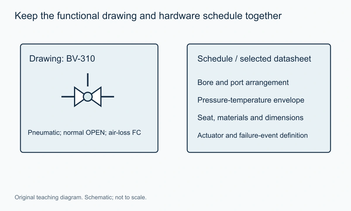
Add the fluid, composition, temperature and pressure range, including the differential during operation and shutoff. For an actuated assembly, provide the available supply and control signal, required speed and defined failure event. For a multiport assembly, attach the port table and transition requirements.
The mechanical scope should identify connection standard, available length, installation orientation and operator access. Product construction belongs in the selected proposal: floating or trunnion support, body arrangement, seat and stem materials, bore and applicable tests. The basic symbol does not establish those choices.
The documentation guide helps keep the drawing, schedule and selected assembly record consistent. Send the duty through the VantaValve quotation form with a drawing extract that includes the connected equipment and port labels.
FAQs on Ball Valve Symbols
These points resolve common ambiguities left after the body, operator and routes have been read.
Does the centre circle mean a full-port ball valve?
No. A ball-specific detail can identify the mechanism in the applicable library, but it does not establish the bore. Full-port and reduced-port constructions can share the same basic functional symbol. Use the selected datasheet and dimensions.
Does a pneumatic operator symbol mean fail closed?
No. Spring arrangement, actuator construction and accessories determine the specified response. State the failure event and required final position or port route. Pneumatic identifies the source of operating force, not a universal failure action.
Can an L-port valve always shut off all three ports?
That depends on the selected bore, stops and seating arrangement. Some applications use two diverting end positions without an intended all-closed position. Define the required routes and obtain the selected product's position table.
Is the drawing symbol a field operating instruction?
It is part of the functional documentation. Field operation must also follow the approved procedure and actual equipment identification. A schematic can omit physical access, local conditions and the sequence needed for a particular task.
Conclusion
Read a ball valve symbol in layers: identify the valve body from the legend, add the operator and defined action, then map every connected port. For multiport valves, a position table is often the clearest way to remove ambiguity.
Use the drawing to establish function and the supporting documents to establish construction, ratings and dimensions. That separation turns a small graphic into a reliable starting point for specification without asking it to communicate information it does not contain.
Need a valve for your application?
Send your valve type, operating conditions and quantity. Our team can help review the options for your inquiry.
Request a Quote →